Download
1 / 41
410 likes | 522 Views
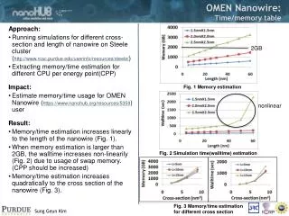
This study explores the impact of band structure on transport in nanowire MOSFETs, aiming to improve device performance by utilizing gate-all-around architectures, new materials, and carrier mobility enhancement. The research delves into scaling transistors into nanoscale dimensions, examining different materials and crystallographic orientations and theoretical aspects related to 3D architectures. The study presents results on effective masses in different materials and valleys, with a focus on enhancing current through optimizing cross-section dimensions. The influence of band structure on silicon and germanium nanowires is also discussed, emphasizing the need for atomistic simulations to understand electrical properties accurately. Utilizing a tight-binding model and band structure calculations, the research aims to enhance wave function descriptions for improved device design.

E N D
Transport in nanowire MOSFETs: influence of the band-structure M. Bescond IMEP – CNRS – INPG (MINATEC), Grenoble, France Collaborations: N. Cavassilas, K. Nehari, M. Lannoo L2MP – CNRS, Marseille, France A. Martinez, A. Asenov University of Glasgow, United Kingdom SINANO Workshop, Montreux 22nd of September
Motivation: improve the device performances Gate-all-around MOSFET: materials and orientations Ballistic transport within the Green’s functions Tight-binding description of nanowires Conclusion Outline 2
Towards the nanoscale MOSFET’s • Scaling of the transistors: New device architectures Improve potential control Gate-all-around MOSFET1: Increasing the number of gates offers a better control of the potential New materials and orientations Improve carrier mobility • Ge, GaAs can have a higher mobility than silicon (depends on channel orientation). • Effective masses in the confined directions determine the lowest band. • Effective mass along the transport determines the tunnelling current. 1M. Bescond et al., IEDM Tech. Digest, p. 617 (2004). 3
3D Emerging architectures • 3D simulations: The gate-all-around MOSFET
Gate-All-Around (GAA) MOSFETs TSi=WSi=4nm TOX=1nm • Source and drain regions: N-doping of 1020 cm-3. • Dimensions: L=9 nm, WSi=4 nm, and TSi=4 nm, TOX=1 nm. • Intrinsic channel. 5
ith eigenstate of the nth atomic plan 3D Mode-Space Approach* 1D (transport) The 3D Schrödinger = 2D (confinement) + 1D ( transport) 2D (confinement) • 3D Problem = N1D Problems Saving of the computational cost!!!! • Hypothesis: n,i is constant along the transport axis. * J. Wang et al., J. Appl. Phys. 96, 2192 (2004). 6
Different Materials and Orientations + Effective Mass Tensor (EMT) Ellipsoid coordinate system (kL, kT1, kT2) Device coordinate system (X, Y, Z) + Rotation Matrices 8
Theoretical Aspects* • 3D Schrödinger equation: Potential energy H3D: 3D device Hamiltonian Coupling * F. Stern et al., Phys. Rev. 163, 816 (1967). 9
Theoretical Aspects* • The transport direction X is decoupled from the cross-section in the 3D Schrödinger equation: Coupling • Where E’ is given by: • mtrans is the mass along the transport direction: • M. Bescond et al., Proc. ULIS Workshop, Grenoble, p.73, April 20th-21st 2006. • M. Bescond et al. JAP, submitted, 2006. 10
ith eigenstate of the nth atomic plane 3D Mode-Space Approach 1D (transport) The 3D Schrödinger = 2D (confinement) + 1D ( transport) 2D (confinement) • Resolution of the 2D Schrödinger equation in the cross-section: mYY, mZZ, mYZ. • Resolution of the 1D Schrödinger equation along the transport axis: mtrans. 11
-valleys Semiconductor conduction band • Three types of conduction band minima: Electron Energy • (ellipsoidal): mlmt non diagonal EMT • (ellipsoidal): mlmt non diagonal EMT E E EΔ • (spherical): ml=mt diagonal EMT -valleys 12
Results: effective masses • Wafer orientation: <010> 13
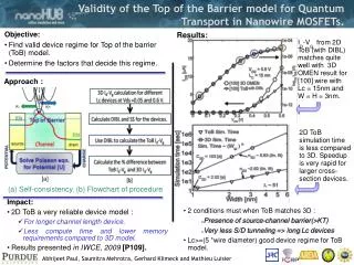
Material: Ge • Square cross-section: 44 nm, <100> oriented wire mYY=0.2*m0mZZ=0.95*m0mtrans=0.2*m0 Z 4-valleys 1st 2nd mYY=0.117*m0mZZ=0.117*m0mYZ-1=±1/(0.25*m0) mtrans=0.6*m0 6 nm -valleys Free electron mass Non-diagonal terms in the effective mass tensor couple the transverse directions in the -valleys 14
Material: Ge • Square cross-section: TT=55 nm, <100> oriented wire • Total current is mainly defined by the electronic transport through the -valleys (bulk) • Tunneling component negligible due to the value of mtransin the -valleys (0.6*m0) 15
Material: Ge • Square cross-section: 44 nm, <100> oriented wire 4-valleys: mYY=0.2*m0, mZZ=0.95*m0 -valleys: mYY=0.117*m0, mZZ=0.117*m0 The 4 become the energetically lowest valleys due to the transverse confinement 16
Material: Ge* 4-valleys: mtrans=0.2*m0 versus -valleys: mtrans=0.6*m0 The total current increases by decreasing the cross-section! * M. Bescond et al., IEDM Tech. Digest, p. 533 (2005). 17
3D Emerging architectures • Influence of the Band structure: Silicon
Why? • Scaling the transistor size • devices = nanostructures • Electrical properties depend on: • Band-bap. • Curvature of the bandstructure: effective masses. • Atomistic simulations are needed1,2. • Aim of this work: describe the bandstructure properties of Si and Ge nanowires. 1J. Wang et al. IEDM Tech. Dig., p. 537 (2005). 19 2K. Nehari et al. Solid-State Electron.50, 716 (2006).
Concept: Develop the wave function of the system into a set of atomic orbitals. sp3 tight-binding model: 4 orbitals/atom: 1 s + 3 p Interactions with the third neighbors. Three center integrals. Spin-orbit coupling. Tight-Binding method Band structure calculation 3rd (12) Diamond structure: 2nd (12) 1st (4) Reference 20
Tight-Binding method Band structure calculation • 20 different coupling terms for Ge:* • Coupling terms between atomic orbitals are adjusted to give the correct band structure: semi-empirical method. * Y.M. Niquet et al. Phys. Rev. B, 62 (8):5109-5116, (2000). 21 *Y.M. Niquet et al., Appl. Phys. Lett. 77, 1182 (2000).
Simulated device Si Nanowire Gate-All-Around transistor Silicon Hydrogen Schematic view of a Si nanowire MOSFET with a surrounding gate electrode. Electron transport is assumed to be one-dimensional in the x-direction. The dimensions of the Si atomic cluster under the gate electrode is [TSix(W=TSi)xLG]. 22
-valleys Energy dispersion relations • In the bulk: The minimum of the conduction band is the DELTA valleys defined by six degenerated anisotropic bands. Constant energy surfaces are six ellipsoids 23
Energy dispersion relations T=2.72 nm T=5.15 nm T=1.36 nm Energy dispersion relations for the Silicon conduction band calculated with sp3 tight-binding model. The wires are infinite in the [100] x-direction. • Direct bandgap semiconductor • The minimum of D2 valleys are zone folded, and their positions are in k0=+/- 0.336 • Splitting between D4 subbands 24
Conduction band edge and effective masses Bandgap increases when the dimensions of cross section decrease m* increases when the dimensions of cross section decrease : 25
Results Current-Voltage Caracteristics 2.98 nm 1.9 nm 1.36 nm ID(VG) characteristics in linear/logarithmic scales for three nanowire MOSFET’s (LG=9nm, VD=0.7V) with different square sections. • No influence on Ioff, due to the reduction of cross section dimension which induces a better electrostatic control • Overestimation of Ion (detailled on next slide) 26
Results Overestimation on ON-Current When the transverse dimensions decrease, the effective masses increase and the carrier velocity decreases. Overestimation of the Ion current delivered by a LG=9nm nanowire MOSFET as a function of the wire width when using the bulk effective-masses instead of the TB E(k)-based values. K. Nehari et al., Solid-State Electronics, 50, 716 (2006). K. Nehari et al., APL, submitted, 2006. 27
3D Emerging architectures • Influence of the Band structure: Germanium
-valleys Conduction band minima • Three types of conduction band minima: • L point: four degenerated valleys (ellipsoidal). • point: single valley (spherical). • directions: six equivalent minima (ellipsoidal). -valleys 29
2 bulk valleys 4 bulk valleys 4 bulk valleys Single bulk valley 4 bulk valleys Dispersion relations* T=5.65 nm Ge <100> • Indirect band-gap. • The minimum of CB obtained in kX=/a corresponding to the 4 bulk valleys. • Second minimum of CB in kX=0, corresponding to the single bulk valley (75% of s orbitals). *M. Bescond et al. J. Comp. Electron., accepted (2006). 30
Dispersion relations Ge <100> T=1.13 nm • The four bands at kX=/a are strongly shifted. • The minimum of the CB moves to kX=0. • The associated state is 50% s ( character) and 50% p ( and character) Quantum confinement induces a mix between all the bulk valleys. • These effects can not be reproduced by the effective mass approximation (EMA). 31
Effective masses: point Ge <100> (1/m*)=(4 ²/h²)( ²E/ k²) • Significant increase compared to bulk value (0.04m0): • From 0.071m0 at T=5.65nm to 0.29m0 at T=1.13nm increase of 70% and 600% respectively. • Other illustration of the mixed valleys discussed earlier in very small nanowires. 32
Effective masses: kX=/a Ge <100> • Small thickness: the four subbands are clearly separated and gives very different effective masses. • Larger cross-sections (D>4nm): the effective masses of the four subbands are closer, and an unique effective mass can be calculated: around 0.7m0 (effective mass: mtrans=0.6m0 for T=5nm) • The minimum is not obtained exactly at kX=/a: 33
Band-gap: Ge vs Si Ge <100> • For both materials: the band gap increases by decreasing the thickness T (EMA). • EG of Ge increases more rapidly than the one of Si: Si and Ge nanowires have very close band gaps. • Beneficial impact for Ge nano-devices on the leakage current (reduction of band-to-band tunneling). 34
Effective masses: Valence Band • Strong variations with the cross-section: from -0.18m0 to -0.56m0 (70% higher than the mass for the bulk heavy hole). 35
Conclusion • Study of transport in MOSFET nanowire using the NEGF. • Effective Mass Approximation: different materials and orientations (T>4-5nm). • Thinner wire: bandstructure calculations using a sp3 tight-binding model. • Evolution of the band-gap and effective masses. • Direct band-gap for Si and indirect for Ge except for very small thicknesses (« mixed » state appears at kX=0). • Bang-gap of Ge nanowire very rapidly increases with the confinement: band-to-band tunneling should be attenuated. • Ge is much more sensitive then Si to the quantum confinement necessity to use an atomistic description + Full 3D* * A. Martinez, J.R. Barker, A. Asenov, A. Svizhenko, M.P. Anantram, M. Bescond, J. Comp. Electron., accepted (2006) * A. Martinez, J.R. Barker, A. Svizenkho, M.P. Anantram, M. Bescond, A. Asenov, SISPAD, to be published (2006) 36
+ • Due to the Fermi-Dirac distribution (1 e-/state) which limits the electron injection in the active region Resistance of the reservoirs • Rq: If bosonic particles: Description of ballisticity: the Landauer’s approach 1D case: Concept of conduction channel and quantum of conductance • Current density from Left to right: • Total current density: • Quantum of conductance: extra
Resistance of the reservoirs Resistance of the reservoirs: the Fermi-Dirac distribution limit the electron quantity injected in a subband (D0=2e2/h). extra
Towards the nanoscale MOSFET’s 1971 1989 1991 2001 2003 410M 42M 1.2M transistors /chip 134 000 2300 Channel length of ultimate R&D MOSFETs in 2006 10 µm 1 µm 0.1 µm 10 nm De Broglie length in semiconductors quantum effects Mean free path in perfect semiconductors ballistictransport extra
E(k) Parabolic approximation of an homogeneous material Parabolic approximation of a finished system of atoms 0 k Semi-empirical methods Effective Mass Approximation (EMA): • Near a band extremum the band structure is approximated by an parabolic function: (Infinite system at the equilibrium) extra
Numerical Aspects • Simulation Code • Potential energy profile (valley (010)) Electrostatic potential 2D Schrödinger Resolution 1D density (Green) Self-consistent coupling 3D density (Green) New electron density Poisson (Neumann) New electrostatic potential The transverse confinement involves a discretisation of the energies which are distributed in subbands Current Extra