Download
1 / 28
290 likes | 303 Views
Learn how collaboration diagrams and sequence diagrams are used to specify interactions and system structures in software modeling, with classifier roles and transient links discussed in detail.

E N D
Interaction Diagrams Spring 2001
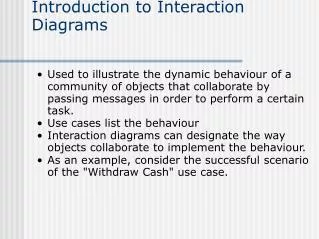
Introduction • Class diagrams • are used to specify the static structure of a system • Object diagrams • are used to illustrate potential states of the system • are typically used only for illustrative purposes • To specify an interaction, it must be stated which messages will be sent, in which order, and under which circumstances. • collaboration diagrams and sequence diagrams are referred to as interaction diagrams • two types of diagram provide alternative ways of expressing the same information
Collaborations • Interactions are illustrated by adding messages to an object diagram • In order to achieve the required generality, interaction diagram in UML are based on the general notion of a collaboration, rather than on object diagrams. • A collaboration is a general description of the ways in which objects can be linked together in order to support the behavior to be supported. • Collaborations are related to class diagrams, as both of them specify ways in which objects can be linked together.
Collaborations (cont’d) • Collaborations specify only those which are relevant to a particular type of interaction. • whereas class diagrams specify all the possible object structures in a system • Collaborations are defined not simply in terms of classes, but rather in terms of the roles that instances of those classes can play in various interactions
Classifier Roles • Collaborations consists of roles • A role describes a particular way in which an object can participate in an interaction. • A classifier role describes a role that objects can play in interactions • Notation for a classifier role : the name of the role and its base class
Association Roles • A collaboration consists of a number of classifier roles connected by association roles • It consists of three classifier roles, linked by two association roles • for finding the cost of a part in the stock control program
Transient Links • An association between two classes implies that instances of the classes can be linked and messages sent between them. • Short lived links are known as transient links • situations in which objects are able to communicate • to distinguish transient links from links that are instances of associations.
Transient Links • Parameter ‘part’ is used as the name of the corresponding classifier role, and the association role connecting to the assembly object is labeled with the appropriate stereotype to indicate that this link exists because of the parameter that was passed.
Interaction Diagram • Sequence diagram • showing classifier roles only, but making the sequencing of messages very clear. • Collaboration diagram • showing classifier and association roles, and superimposing messages on association roles • The major difference between the two forms of diagram is the way they show the order in which message are sent.
Sequence Diagrams • The classifier roles involved in the interaction are displayed at the top of the diagram • Each role has a dashed line, known as its lifeline • Activation : the period of time during which an object is processing a message designated as a narrow rectangle whose top is connected to a message.
Collaboration Diagrams • Unlike sequence diagram, collaboration diagrams show association as well as classifier roles • messages sequencing cannot be shown graphically
Collaboration Diagrams (cont’d) • Hierarchical numbering of messages • reflecting explicitly the structure of nested activations
Object Creation • The relationship between orders and order lines is one of composition, because we assume that when an order is destroyed all lines of that order are also destroyed.
Object Creation (cont’d) • Object creation on a sequence diagram
Object Creation (cont’d) • Object creation on a collaboration diagram • In order to distinguish elements that are created during the course of an interaction from those which existed at the start, classifier and association roles corresponding to new objects and links are annotated with the property ‘new’.
Object Destruction • Messages which cause the destruction of objects are labeled with the stereotype ‘destroy’.
Object Destruction (cont’d) • Object deletion on a collaboration diagram
Iterated Messages • Showing a collaboration which uses this notation to show that an assembly involved in an interaction can contain zero or more components. • Classifier roles and multiplicity
Iterated Messages (cont’d) • In order to find out the cost of an assembly, a message must be sent to each of the components, no matter how many there are. • To emphasize the fact that a single symbol could correspond to multiple messages, notation is added to message label to indicate an iterated message send. • Iterated message passing on a collaboration diagram
Iterated Messages (cont’d) • Iteration diagram passing on a collaboration diagram
Multiobjects • An alternative way of showing multiplicity information associated with a classifier role is to use a multiobject. • a multipoint represents a collection of objects of the base type of the multiobject • Showing multiplicity with a multiobject
Multiobjects (cont’d) • Showing an order object sending a message to a collection of order lines, asking for the line which corresponds to the catalogue entry with part number ‘n’.
Multiobjects (cont’d) • Finding the total cost of an order
Conditional Messages • A boolean expression written in square brackets
Conditional Messages (cont’d) • Condition messages on collaboration diagrams
Conditional Messages (cont’d) • Alternative messages on a sequence diagram
Conditional Messages (cont’d) • Messages to Self
Conditional Messages (cont’d) • Recursive activations are not shown so explicitly on collaboration diagram but, each recursive activation gives rise to an extra level of hierarchy in the numbering of subsequent messages