Download
1 / 13
550 likes | 1.53k Views
FREQUENCY RESPONSE. ELEC 202 Circuit Analysis II. The frequency response of a circuit is the variation in its behavior due to the change in signal frequency. Measured in terms of the variation of the gain and phase as a function of frequency

E N D
FREQUENCY RESPONSE ELEC 202 Circuit Analysis II
The frequency response of a circuit is the variation in its behavior due to the change in signal frequency. • Measured in terms of the variation of the gain and phase as a function of frequency • Vary the frequency of the input signal source (i.e. sinusoid) while keeping its amplitude constant • Important in filter design Introduction
For a circuit with a sinusoidal input source, its frequency response is defined as the ratio of its phasor output to its phasor input, expressed as a function of frequency. Definition
Characteristics Typically expressed as an irreducible ratio of two polynomials in frequency (i.e., the common numerator and denominator factors have canceled, reducing the ratio to the lowest terms) When working with , temporarily replace with s to avoid complex algebra
Characteristics (Cont’d) Roots of the numerator polynomial are called the zeros of Roots of the denominator polynomial are called the poles of
The Decibel Scale The use of a logarithmic scale to express gain (either power, voltage or current) The 10log is used for power, while 20log is used either for voltage or current. The two quantities in the ratio must be of the same type.
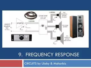
Example For the RC circuit shown, determine and sketch its frequency response.
Magnitude Response Phase response
Example For the RL circuit shown, determine and sketch its frequency response.
Magnitude Response Phase response
Example For the circuit shown, determine the gain and its poles and zeros.
Example For the circuit shown, determine its transfer impedance and obtain its poles and zeros.