Download
1 / 17
170 likes | 286 Views
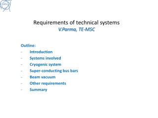
Workshop on cryogenic and vacuum sectorisations of the SPL CERN, 9 th -10 th November 2009 Workshop Organisation and Goals. Vittorio Parma TE-MSC. Agenda. Layout injector complex. SPS. PS2. ISOLDE. PS. SPL. We are here today. Linac4. The SPL study. Goals of the study (2008-2012):

E N D
Workshop on cryogenic and vacuum sectorisations of the SPLCERN, 9th -10th November 2009Workshop Organisation and Goals Vittorio Parma TE-MSC
Layout injector complex SPS PS2 ISOLDE PS SPL We are here today Linac4
The SPL study Goals of the study (2008-2012): • Prepare a Conceptual Design Report with costing to present to CERN’s management for approval • …aimed at a start of construction of the low power SPL (LP-SPL) optimized for PS2 and LHC at the beginning of 2013 110 m 0.73 GeV 186 m 1.4 GeV 0 m 0.16 GeV 427 m 4 GeV 10 x 6 b=0.65 cavities 13 x 8 b=1 cavities 5 x 8 b=1 cavities High b cryomodules High b cryomodules Debunchers Medium b cryomodule To PS2 Ejection From Linac4 Length: ~430 m TT6 to ISOLDE LP-SPL beam characteristics
The SPL study (cont.d) • … with an optional possibility of a later upgrade to 5 GeV and multi MW high power beam (HP-SPL). ~500 m 5GeV 110 m 0.73 GeV 186 m 1.4 GeV ~300 m 2.5 GeV 0 m 0.16 GeV High b cryomodules Ejection 10 x 6 b=0.65 cavities 6 x 8 b=1 cavities 5 x 8 b=1 cavities High b cryomodules High b cryomodules Medium b cryomodule Debunchers To PS2 Ejection From Linac4 12 x 8 b=1 cavities to Eurisol Length: ~500 m TT6 to ISOLDE HP-SPL beam characteristics
Construction of a cryo-module prototype (as part of the SPL study) today
Topics for discussion • What is already decided (not for discussion today): • Cavities cooled in saturated superfluid helium (T~ 2K, P~ 3.1 kPa) • Cavities RF frequency: 704 MHz • One surface cryoplant at mid lenght of the SPL: • ~ 6 MW @ 4.5K for LP-SPL (~ 20 MW @ 4.5K for HP-SPL) • What is to be discussed today: • Cryogenic cooling layouts and schemes and consequences on machine cryostats: • Single “continuous” cryostat vs. fully “segmented” cryostat with cryo distribution line • Intermediate variants • Vacuum systems and consequences on machine cryostats: • Insulation vacuum and need for vacuum barriers • Cavity/beam vacuum and need for gate valves • possibly also coupler vacuum • We need to learn from the experience of other machines and labs
Road map of the workshop • Machine availability: • “work-horse” in the injection chain • 100% availability not viable,.What is achievable? And at which cost? • Reliability of built-in components and operational risks (degraded performance without intervention) • Typical faults expected on: • Cavities • Couplers • Tuners • .. • Operation with degraded performance and mitigating measures: • Degraded performance of cavity/ies reduced energy • Degraded optics (quads, steerers) reduced beam quality • Operating with leaks • ... • Built-in redundancy (e.g. need for installed spare cryo-modules) • Maintainability: • Radioactive cool-down time • Warm-up/cool-down . Time and reliability. Need for partial or complete warm-up of strings to replace built-in components or even one cryo-module • Accessability of components for regular maintenance or repair • Design complexity of compared solutions • Operational complexity (e.g.cryogenics with 1.7% slope) • Installation and commissioning • Coping with incidents (MCI). Loss of beam and/or insulation vacuum : • helium leaks • Air leaks • Cost differences between options • - …
Goals • Primary goals: • Identify the main operational and intervention scenarios for the cryogenics and vacuum systems of the SPL • Elaborate an exhaustive technical and economical comparison between single “continuous” cryostat and “segmented” cryostat with cryo distribution line • Possibly reccomend a choice between the two options • Define a “baseline” cryogenic distributions scheme and vacuum sectorisation • Elaborate, if necessary, a list of further developments for making a choice • Other goals: • Identify advantages for alternative sectorisation schemes (intermediate solutions) • Technical comparison between layouts with warm and cold magnets • Identify other machine architectures to be explored for an improved sectorisation (e.g. alternative optic schemes)
Possible cryogenic feeding Cryo-plant 1.7% tunnel slope CIB 10 β=0.65 + 5 β=1 cryo-modules 6 β=1 cryo-modules 17 β=1 cryo-modules + 2 demodulators Isolde extraction Eurisol extraction CIB Cryogenic Interconnect Box Cryo Unit Cryogenic bridge
Possible cryogenic feeding Cryo-plant CIB 10 β=0.65 + 5 β=1 cryo-modules 6 β=1 cryo-modules 17 β=1 cryo-modules + 2 demodulators Isolde extraction Eurisol extraction CIB Cryogenic Interconnect Box Cryo Unit Cryogenic bridge
Possible cryogenic feeding Cryo-plant CIB 10 β=0.65 + 5 β=1 cryo-modules 6 β=1 cryo-modules 17 β=1 cryo-modules + 2 demodulators Isolde extraction Eurisol extraction CIB Cryogenic Interconnect Box Cryo Unit Local Cryo Distribution Line (~80m)
Possible cryogenic feeding Cryo-plant CIB 10 β=0.65 + 5 β=1 cryo-modules 6 β=1 cryo-modules 17 β=1 cryo-modules + 2 demodulators Isolde extraction Eurisol extraction CIB Cryogenic Interconnect Box Cryo-module Units Cryogenic Distribution Line
“continuous” cryostat • “Long” and “continuous” string of cavities in common cryostat • Cold beam tube • “straight” cryogenic lines in main cryostat • common insulation vacuum (between vacuum barriers, if any present) String of cryo-modules between TSM Technical Service Module (TSM) Cold-Warm Transition (CWT) Insulation vacuum barrier Warm beam vacuum gate valve
“bridged” cryostat • Variant of the continuous cryostat • Warm beam zones, 2 CWT at every cryo-module • cryostat “bridges” between adjacent cryo-modules • “bent” cryogenic lines through “bridges” CDL not needed • common insulation vacuum (between Vacuum Barriers, if any present) Cryostat “bridge” with integrated cryo-lines Single cryo-modules Technical Service Module (TSM) Cold-Warm Transition (CWT) Insulation vacuum barrier Warm beam vacuum gate valve
“segmented” cryostat • Cryostat is “segmented”: strings of (or single) cryo-modules, 2 CWT each • Warm beam zones • Cryogenic Distributio Line (CDL) needed • Individual insulation vacuum on every string of cryo-module (Vacuum Barriers, w.r.t. CDL) Cryogenic Distribution Line (CDL) String of (or single) cryo-modules Technical Service Module (TSM) Cold-Warm Transition (CWT) Insulation vacuum barrier Warm beam vacuum gate valve