Download
1 / 55
610 likes | 1.25k Views
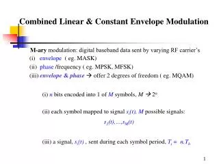
6.9 Constant Envelope Modulation. 6.9.1 BFSK 6.9.2 MSK 6.6.3 GMSK. 6.9 Constant Envelope Modulation. nonlinear modulation constant carrier amplitude - regardless of variations in m(t) improved power efficiency without degrading occupied spectrum

E N D
6.9 Constant Envelope Modulation 6.9.1 BFSK 6.9.2 MSK 6.6.3 GMSK
6.9 Constant Envelope Modulation • nonlinear modulation • constant carrier amplitude - regardless of variations in m(t) • improved power efficiency without degrading occupied spectrum • - use power efficient class Camplifiers (non-linear) • low out of band radiation (-60dB to -70dB) • use limiter-discriminator detection • - simplified receiver design • - high immunity against random FM noise & fluctuations from • Rayleigh Fading • larger occupied bandwidth than linear modulation
sBFSK(t)= vH(t) = binary 1 6.95 sBFSK(t)= vL(t) = binary 0 • 6.9.1 BFSK • constant amplitude carrier • carrier frequency switched between 2 values – 2 message states • implementation determines if phase between bits is continuous • or discontinuous General FSK signal • 2f = constant offset from nominal carrier frequency • Methods for Generating BFSK signals • (i) shift between 2 independent oscillators • (ii) modulate a single carrier
input data phase jumps cos w1t switch cos w2t = sBFSK(t)= vH(t) binary 1 6.96 binary 0 sBFSK(t)= vL(t) • (i) switching between 2 independent oscillators for binary 1 & 0 • results in phase discontinuities • discontinuities causes spectral spreading & spurious transmission • not suitedfor tightly designed systems =
sBFSK(t) = = where (t) = ii. single carrier that is frequency modulated using m(t) 6.97 • m(t) = discontinuous bit stream • (t) = continuous phase function proportional to integral of m(t)
x a0 a1 0 1 VCO 0 1 1 modulated composite signal cos wct
Spectrum & Bandwidth of BFSK Signals • complex envelope of BFSK is nonlinear function of m(t) • evaluation of spectrum is difficult • usually performed using actual time averaged measurements • PSD of BFSK consists of discretefrequency components at • fc • fc nf • PSD decay rate (inversely proportional to spectrum) • PSD decay rate for CP-BFSK • PSD decay rate for non CP-BFSK • f = frequency offset fromfc
Transmission Bandwidth of BFSK Signals (from Carson’s Rule) • B = bandwidth of digital baseband signal • BT = transmission bandwidth of BFSK signal • BT= 2f +2B 6.98 • assume 1st null bandwidth used for digital signal, B • - bandwidth for rectangular pulses is given by B = Rb • - bandwidth of BFSK using rectangular pulse becomes • BT = 2(f + Rb) 6.99 • if RC pulseshaping used, bandwidth reduced to: • BT = 2f +(1+) Rb6.100
cos wct output + - Decision Circuit r(t) sin wct Probability of error in coherent FSK receiver given as: Pe,BFSK = 6.101 • Coherent BFSK Detector • 2 correlators fed with local coherent reference signals • difference in correlator outputs compared with threshold to • determine binary value • block diagram is optimum for coherent BFSK in AWGN channel Decision Circuit: if output > Threshold ‘1’ else ‘0’
Matched Filter fH + - Envelope Detector r(t) output Tb Decision Circuit Envelope Detector Matched Filter fL Pe,BFSK, NC = 6.102 • Non-coherent Detection of BFSK • operates in noisy channel without coherent carrier reference • pair of matched filters followed by envelope detector • - upper path filter matched to fH (binary 1) • - lower path filter matched to fL (binary 0) • envelope detector output sampled at kTb compared to threshold Average probability of error in non-coherent FSK receiver:
General FSK signal and orthogonality • Two FSK signals, VH(t) and VL(t) are orthogonal if 6.103 • interference between VH(t) and VL(t) will average to 0 during • demodulation and integration of received symbol received signal will contain VH(t) and VL(t) demodulation of VH(t) results in (VH(t) + VL(t))VH(t)
vH(t) = for 0 ≤ t ≤ Tb and vL(t) = then and vH(t)vL(t) = = = = General FSK signal vH(t)vL(t) areorthogonal if Δf sin(4πfcTb) = -fc(sin(4πΔf Tb)
consider binary CPFSK signal defined over the interval 0 ≤ t ≤ T s(t) = • θ(t) = phaseof CPFSK signal • θ(t) is continuous s(t) is continuous at bit switching times • θ(t) increases/decreases linearly with t during T θ(t) = θ(0) ± ‘+’ corresponds to ‘1’ symbol ‘-’ corresponds to ‘0’ symbol h = deviation ratio of CPFSK CPFSK Modulation • elimination of phase discontinuity improves spectral efficiency & • noise performance 0 ≤ t ≤ T
2πfct +θ(0) + = 2πf2 t+θ(0) f1 = 2πfct +θ(0) - = 2πf1t+θ(0) fc= f2 = yields and thus h = T(f2 – f1) determine fc and h by substitution • nominal fc= mean of f1 and f2 • h≡f2 – f1 normalized by T
at t = T θ(T) = θ(0) ± πh kFSK= symbol‘1’ θ(T) - θ(0) = πh symbol‘0’ θ(T) - θ(0) = -πh • peak frequency deviation F = |fc-fi | = ‘1’ sent increases phase of s(t) by πh ‘0’ sent decreases phase of s(t) by πh • variation ofθ(t)with t follows a path consisting of straight lines • slope of lines represent changes in frequency FSK modulation index =kFSK (similar to FM modulation index)
θ(t) - (0) rads 3πh 2πh πh 0 -πh -2πh -3πh 0 T 2T 3T 4T 5T 6T t • Phase Tree depicted from t = 0 • clarifies phase transitions across interval boundaries of incoming • bit sequence • θ(t) - (0) = phase of CPFSK signal is even or even multiple of πh • at even or even multiples of T
θ(t) - (0) 3π 2π π 0 -π -2π -3π fi= f1= 2/T andf2= 3/T fc= = 5/2T 0 T 2T 3T 4T 5T 6T t h = T(f2 – f1) = 1 θ(t) = θ(0) ± 0 ≤ t ≤ T Phase Tree is a manifestation of phase continuity – an inherent characteristic of CPFSK consider Sunde FSK 1 0 0 0 0 1 1 • thus change in phase over T is either πor -π • change in phase of π = change in phase of -π • Sunde FSK has no memory • e.g. knowing value of bit i doesn’t help to find the value of bit i+1
fi= nc = fixed integer assume fi given by as si(t) = 0 ≤ t ≤ T for i = 1, 2 si(t) = 0 ≤ t ≤ T for i = 1, 2 = 0 otherwise = 0 otherwise • Sunde FSK • CPFSK = continuous phase FSK • phase continuity during inter-bit switching times
2(t) 0 for i = 1, 2 i(t) = 0 ≤ t ≤ T 1 1(t) = 0 otherwise Sunde BFSK constellation: define two coordinates as let nc = 2 and T = 1us (1Mbps) then f1= 3MHz,f2 = 4MHz 1(t) = 0 ≤ t ≤ T = 0 otherwise 2(t) = 0 ≤ t ≤ T = 0 otherwise
0 ≤ t ≤ T s1(t) = = 0 otherwise 0 ≤ t ≤ T = = s2(t) = = 0 otherwise
Sunde FSK Tb = 0.01, Rb= 100bps f1= 300Hz, f2= 400Hz two data carriers baseband time domain baseband frequency domain
Demodulation of Sunde FSK using Correlators Autocorrelation Cross Correlation
6.9.2 MSK (aka fast FSK) FSK modulation index • type of continuous phase FSK (CPFSK) • spectrally efficient • constant envelope • good BER performance • self-synchronizing capability • requires coherent detection • minimum frequency spacing (bandwidth) for 2 FSK signals to • be coherently orthogonal • minimum bandwidth that allows orthogonal detection kFSK= MSK modulation index is kMSK= 0.5 FMSK=
MSK can be thought of as special case of OQPSK • uses half-sinusoidal pulses instead of baseband rectangular pulses • arch shaped pulse during period = 2Tb • modify OQPSK equations for half-sine pulses for N-bit stream • several variations of MSK exist with different basic pulse shapes • e.g. • - use only positive ½ sinusoids • - use alternating negative & positive ½ sinusoids • all variations are CPFSK that use different techniques to achieve • spectral efficiency
sMSK(t) = • mI(t) & mQ(t)are bipolar bit streams (1) that feedI& Q • arms of the modulator - each arm fed at Rb/2 6.104 • mIi(t) = ith bit of mI(t), the even bits of m(t) • mQi(t) = ith bit of mQ(t), the odd bits of m(t) ½ sine pulse given by p(t) = 6.105 p(t – 2iTb)cos(2πfct) m(t) = ±1 bipolar bit stream p(t – 2iTb-Tb)sin(2πfct) TransmittedMSK signal (OQPSK variant)
sMSK(t) = 6-106 • k= 0 or depending on whether mI(t) = +1 to -1 • sMSK(t) has constant amplitude • to ensure phase continuity at bit interval selectfc = • - n = integer • fc - and • fc + rewrite 6.104 view MSK waveform as a special case of CPFSK MSK is FSK signal with binary signaling frequencies given by • phase of MSK varies linearly over Tb
Phase Continuity of MSK h = ½ θ(t) = θ(0) ± 0 ≤ t ≤ T phase, θ(t) can take on only 2 values at odd or even multiples of T t =even multiple of T θ(T) - θ(0)= πor 0 t = odd multiple of Tθ(T) - θ(0)= ± π/2 assume = θ(0) 0
π π/2 0 -π/2 -π θ(t) - (0) 1 0 0 1 1 1 0 0 2T 4T 6T t Phase Trellis: path depicts θ(t) corresponding to a binary sequence • for h = ½ ΔF = Rb/4 • minimum ΔF for two binary FSK signals to be coherently • orthogonal • e.g. if Rb = 100Mbps = ΔF = 25MHz
and f1 = f2 = then fc= = 1/T h = T(f1 - f2) = 1/2 θ(t) = θ(0) ± 0 ≤ t ≤ T MSK signal can be expressed as = s(t) = assume θ(0)= 0, then if bit = ‘1’ then s(t) = if bit = ‘0’ then s(t) = e.g. assume MSK modulation with
define orthonormal basis for MSK as 1(t) = 2(t) = 0 ≤ t ≤ T 0 ≤ t ≤ T bi θ(0) θ(T) s1 s2 then s(t) = s1(t)1(t) + s2(t)2(t) with ‘0’ 0 -π/2 ‘1’ π -π/2 s1= -T ≤ t ≤ T ‘0’ π π/2 ‘1’ 0 π/2 s2= = 0 ≤ t ≤ 2T =
RF power spectrum obtained by frequency shifting |F{p(t)}|2 • F{} = fourier transform • p(t)= MSK baseband pulse shaping function (1/2 sin wave) p(t) = 6.107 Normalized PSD for MSK is given as PMSK(f) = 6.108 MSK Power Spectrum
PSD of MSK & QPSK signals 10 0 -10 -20 -30 -40 -50 -60 QPSK, OQPSK MSK normalized PSD (dB) fc fc+0.5Rb fc+Rb fc+1.5Rb fc+2Rb • MSK spectrum • (1) has lower side lobes than QPSK (amplitude) • (2) has wider side lobes than QPSK (frequency) • 99% MSK power is within bandwidthB = 1.2/Tb • 99% QPSK power is within bandwidth B = 8/Tb
MSK has faster roll-off due to smoother pulse function • Spectrum of MSK main lobe > QPSK main lobe • - using 1st null bandwidth MSK is spectrally less efficient • MSK has no abrupt phase shifts at bit transitions • - ok to bandlimit MSK signal to meet specified bandwidths • - bandlimiting doesn’t cause envelop to cross 0 • - envelope is constant after bandlimiting • small variations in envelope removed using hardlimiting • - does not raise out of band radiation levels • constant amplitude non-linear amplifiers can be used • continuous phase is desirable for highly reactive loads • simple modulation and demodulation circuits
mI(t) _ + SMSK(t) + + mQ(t) + + cos(2fct) cos(t/2T) MSK Transmitter (i) cos(2fct)cos(t/2T) 2 phase coherent signals atfc ¼R (ii) Separate 2 signals with narrow bandpass filters (iii) Combined to formI & Q carrier components x(t), y(t) (iv) Mix and sum to yield SMSK(t) = x(t)mI(t) + y(t)mQ(t) x(t) y(t)
(i) multiplycos(2fct)cos(t/2T) • cos(2fct) =carrier • cos(t/2T) =baseband pulseshaping function • produces two phase coherent signals atfc ¼R • (ii) Separate 2 FSK signals with narrow bandpass filters • (iii) Combined to form • I carrier component: x(t) = (fc - 1/4Tb) – (fc + 1/4Tb) = -1/2Tb • Q carrier component y(t) = (fc + 1/4Tb) + (fc-1/4Tb) = 2fc if fc = 1/4Tb 2fc = 1/2Tb MSK Transmitter • (iv) SMSK(t) = x(t)mI(t) + y(t)mQ(t) • mI(t) & mQ(t) = even & odd bit streams
Threshold Device mI(t) t = 2(k+1)T x(t) SMSK(t) y(t) Threshold Device mQ(t) t = 2(k+1)T Coherent MSK Receiver • (i) SMSK(t) split & multiplied by local x(t) & y(t) (I & Q carriers) • (ii) mixer outputs are integrated over 2T & dumped • (iii) integrate & dump output fed to decision circuit every 2T • input signal level compared to threshold decide 1 or 0 • output data streams correspond to mI(t) & mQ(t) • mI(t) & mQ(t) are offset & combined to obtain demodulated signal • *assumes ideal channel – no noise, interference
MSK Tb = 0.001, Rb= 1kbps f1=750Hz, f2= 1250Hz two data carriers 1 1 1 0 0 1 0 0 1 baseband time domain baseband frequency domain
Orthogonality Property of MSK Autocorrelation Cross Correlation
6.9.3 GMSK 6.9 Constant Envelope Modulation 6.9.1 BFSK 6.9.2 MSK 6.6.3 GMSK
6.9.3 GMSK Modulation • simple to apply Gaussian pulse shaping MSK • - smooths phase trajectory of MSK signal over time, stabilizes • instantaneous frequency variations • - results in significant additional reduction of sidelobe levels • premodulation pulse shaping filter used to filter NRZ data • - converts full response message signal into partial response • scheme • full response baseband symbols occupy Tb • partial responsetransmitted symbols span several Tb • - pulse shaping doesn’t cause pattern’s averaged phase trajectory • to deviate from simple MSK trajectory • GMSK detection can be coherent (like MSK) or noncoherent • (like FSK)
GMSKs main advantages are • power efficiency - from constant envelope (non-linear amplifiers) • excellent spectral efficiency • pre-modulation filtering introduces ISI into transmitted signal • if B3dbTb > 0.5 degradation is not severe • B3dB= 3dB bandwidth of Gaussian Pulse Shaping Filter • Tb= bit duration = baseband symbol duration • irreducible BER caused by partial response signaling is the • cost for spectral efficiency & constant envelope • GMSK filter can be completely defined form B3dB Tb • - customary to define GMSK by B3dBTb
impulse responseof pre-modulation Gaussian filter given by hG(t) = 6-109 transfer function of pre-modulation Gaussian Filter given by 6-110 HG(f) = is related toB3dB by = 6.111
ReducingB3dBTb • (i) spectrum becomes more compact (spectral efficiency) • causes sidelobes of GMSK to fall off rapidly • B3dBTb = 0.5 2nd lobe peak is 30dB below main lobe • MSK 2nd peak lobe is 20dB below main lobe • MSK GMSK with B3dBTb = • (ii) increases irreducible error rate (IER)due to ISI • ISI degradation caused by pulse shaping increases • however - mobile channels induceIERdue to mobile’s velocity • mobile channels induce IER due to mobile’s velocity • if GMSK IER < mobile channel IER no penalty for • using GMSK
0 -10 -20 -30 -40 -50 -60 0 0.5 1.0 1.5 2.0 (f-fc)T PSD of GMSK signals BTb = (MSK) BTb = 1.0 BTb = 0.5 BTb = 0.2 • increasing BTb • reduces signal spectrum • results in temporal spreading and distortion
RF bandwidth containing % power as fraction of Rb e.g. for BT = 0.2 99.99% of the power is in the bandwidth of 1.22Rb • [Ish81] BER degradation from ISI caused by GMSK filtering is • minimal at B3dBTb= 0.5887 • degradation in required Eb/N0 = 0.14dB compared to case of no ISI
6.112 Pe = • GMSK BER for AWGN channel • [Mur81] shown to perform within 1dB of optimal MSK with • B3dBTb = 0.25 • since pulse shaping causes ISI Peis function of B3dBTb Pe= bit error probability is constant related to B3dBTb • B3dBTb = 0.25 = 0.68 • B3dBTb = = 0.85 (MSK)