Download
1 / 48
480 likes | 580 Views
Simulations OF TARGETS FOR NDCX II*. J. J. Barnard 1 , J. Armijo 2 , F. M. Bieniosek 2 , A. Friedman 1 , M. Hay 2 , E. Henestroza 2 , B.G. Logan 2 , R. M. More 2 , P. A. Ni 2 , L. J. Perkins 1 , S. F. Ng 2,4 , S. A. Veitzer 3 , J. S. Wurtele 2 , S. S. Yu 2,4 , A. B. Zylstra 2

E N D
Simulations OF TARGETS FOR NDCX II* J. J. Barnard1, J. Armijo2, F. M. Bieniosek2, A. Friedman1, M. Hay2, E. Henestroza2, B.G. Logan2, R. M. More2, P. A. Ni2, L. J. Perkins1, S. F. Ng2,4, S. A. Veitzer3, J. S. Wurtele2, S. S. Yu2,4, A. B. Zylstra2 1. Lawrence Livermore National Laboratory, Livermore, CA 94550, USA 2. Lawrence Berkeley, National Laboratory, Berkeley, CA 94720 USA 3. Tech-X Corporation, Boulder, CO 80303 USA 4. Chinese University, Hong Kong, China Twelfth US-Japan Workshop on Heavy Ion Fusion and High Energy Density Physics San Francisco, CA September 6 – 11, 2009 *Work performed under the auspices of the U.S. Department of Energy under contract DE-AC52-07NA27344 at LLNL, and University of California contract DE-AC02-05CH11231 at LBNL
NDCX II will serve as a platform for warm dense matter experiments and as a test bed for heavy ion fusion 1. Experimental concepts for Warm Dense Matter (WDM) • planar solid targets • metallic foams c. cylindrical "bubbles" d. spherical bubbles 2. Connecting simulations of WDM targets to diagnostics a. simulating brightness temperature at critical density point b. simulating velocity at critical density point • 3. Simulations of experiments relevant to Heavy Ion Fusion (HIF) a. coupling physics: two-pulse/ ramped pulse experiments
Complementary oral talks at IFSA cover other aspects of NDCX I and NDCX II Oral 3.8.1 Frank Bieniosek, Wednesday, 9/9, 3:00 pm ION-BEAM-DRIVEN WARM DENSE MATTER EXPERIMENTS Oral 3.8.2 Alex Friedman, Wednesday, 9/9, 3:20 pm PHYSICS DESIGN FOR NDCX-II, A SHORT-PULSE ION BEAM DRIVER FOR NEAR-TERM WDM AND TARGET PHYSICS STUDIES
NDCX I is laying the groundwork for NDCX II • Explore metal liquid/vapor • boundaries at T ~ 0.4 eV • Evaporation rates/ bubble and droplet formation • Test beam compression physics • Test diagnostics NDCX I 0.35 MeV, 0.003 mC Now • Bragg peak (uniform) heating • T ~1-2 eV in planar metal targets • (higher in cylindrical/spherical • implosions) • Ion+/Ion- plasmas • Critical point; complete liquid/ • vapor boundary • Transport physics (e-cond. etc) • HIF coupling and beam physics NDCX II 3 - 6 MeV, 0.03 mC Completion date: 2011
Several target options have been considered for WDM studies on NDCX II >6 hole diameter Ion beam Ion beam 1 mm spot diameter 1 mm spot diameter Expected regime: ~1.2 eV, 0.2 Mbar 3.5 3.5 Solid planar targets Cylindrical "bubble" targets 1 bubble diameter Foam densities ~ few % to solid Ion beam Ion beam 1 mm spot diameter 1 mm spot diameter Pore size ~ nm to ~ m 35 for 10% foam 3.5 Foam planar targets Spherical bubble targets
The nominal beam assumes a 30 J/cm2 2.8 MeV Li ion beam, corresponding to 20 kJ/g in Al (SRIM) HYDRA/ QEOS SRIM Ion beam 1 mm spot diameter Expected regime: ~1.2 eV, 0.2 Mbar 3.5 Solid planar targets For HYDRA1runs we assume the nominal beam results in 20 kJ/g in Al. This implies the simulated beam had a fluence of 20 J/cm2 (instead of 30 J/cm2) 1. M. M. Marinak, G. D. Kerbel, N. A. Gentile, O. Jones, D. Munro, S. Pollaine, T. R. Dittrich, and S. W. Haan, Phys. Plasmas 8, 2275 (2001).
An example of two significantly different EOS LEOS QEOS Aluminum 0.32 0.32 0.04 0.04 0.01 0.01 + + 0.001 Log[T(keV)] Log[T(keV)] 0.001 0.0 -0.001 -0.001 0.0 Log[r (g/cm3)] Log[r (g/cm3)] Log[r (g/cm3)] Critical point: Critical point: p=0.029 MBar r=0.78 g/cm3 T=0.945 eV p=0.0065 MBar r=0.70 g/cm3 T=0.633 eV Theories and experiments place critical point between 5500 K and 12000 K (0.5 eV and 1.0 eV)
Evolution of center of 3.5 m thick Al foil over the heating phase (1 ns) using QEOS without maxwell construction temperature density pressure Z*
Evolution of center of 3.5 m thick Al foil over the heating phase (1 ns) using QEOS without maxwell construction entropy vz QEOS CP T LEOS CP r
Target evolution was tracked for 30 ns vz Temperature Entropy T r
Critical frequency ncrit defines "over dense" point where wave propagation becomes evanescent Consider idealized case: Energy instantaneously deposited; ideal gas; Z* = constant Density contours cst/L cst/L density z/L z/L For adiabatic evolution lines of constant density coincide with lines of constant temperature (since T ~ rg-1 ).
As estimate of brightness temperature Tb at a given n we may take the black body intensity at the temperature of the critical point Density contours Tb cst/L cst/L z/L - Brightness temperature will stay constant until contour reaches z axis - Brightness temperature will stay constant for longer times at lower frequencies
For the actual target case (QEOS shown here) we may plot hncrit vs z and T(hncrit) vs t for several hncrit's Model assumes: Tb = T(hncrit) if hncritmin < hn < hncritmax Tb = Tmax if hn > hncritmax Tb = 0 if hn < hncritmin hncrit Tmax 150 nm (8.3 eV) (UV) z (microns) 450 nm (2.4 eV) (Green visible) 1500 nm (0.83 eV) (IR)
We may compare the same plots for different intensities Upper set: 20 kJ/gm Middle set: 15 kJ/gm Lower set: 10 kJ/g (Magenta curves: Tmax; Blue curves: 150 nm Green curves: 450 nm; Red curves: 1500 nm) (UV most sensitive to change in deposited energy; IR (which samples cooler part of blowoff, less sensitive)
We may also compare two equations of state Upper set: LEOS without Maxwell construction Lower set: QEOS without Maxwell construction (Magenta curves: Tmax; Blue curves: 150 nm Green curves: 450 nm; Red curves: 1500 nm) Now IR is most sensitive to the EOS, and the two EOS should be distinguishable
We may also compare the same equation of state with or without the Maxwell construction Upper set: LEOS with Maxwell construction Lower set: LEOS without Maxwell construction (Magenta: Tmax; Blue: 150 nm Green: 450 nm; Red: 1500 nm) Now IR is VERY sensitive to the choice of Maxwell construction or no Maxwell construction
We may also calculate the velocity at the critical density for a particular photon frequency as a function of time Again looking at the idealized case (instantaneous heating, ideal gas, constant Z*): The velocity contours first align with, then cross the density and temperature contours, so the velocity measured at the critical density would first be constant then plummet Velocity contours Density contours cst/L cst/L z/L z/L vcritical_dens/cs Time at which density contour reaches z=0 axis Tcritical_dens cst/L cst/L
For realistic equations of state and finite heating time the velocity would also reach zero at the end of the flattop in Tb (Magenta: Velocity of outermost zone; Blue: 150 nm Green: 450 nm; Red: 1500 nm) Upper set: LEOS with Maxwell construction Lower set: QEOS without Maxwell construction Again, the IR is best suited for distinguishing different EOS
eV eV eV eV eV 1.2 2.4 2.5 .67 .056 .051 .51 .90 .42 .42 A cylindrical hole can create regions of temperature and pressure larger than in a simple foil T T T 4 6 Ion beam T T T HYDRA simulations by E. Henestroza (using LEOS). Solid Tin target. 2.8 MeV Li+, 10 J/cm2 assumed. Tmax = 2.6 eV; Pmax = 1.3 Mbarmax= 11 g/cm3 (init= 7 g/cm3 ); vimp = 3.5 km/s Advantage: relatively easy to manufacture and diagnose
If instead of a cylindrical hole, a spherical void is placed in the foil, higher pressures are possible 1 bubble diameter Simulation: 0.5 0.5 Ion beam radius (m) 1.75 3.5 Deposition: 25 kJ/g/ns for 1 ns Simulations by Siu-Fai Ng (using DISHr, QEOS) Pmax > 10 Mbar, Tmax > 10 eV, max > 5 g/cm3 0 t (ns) 0.250 10M 10 5 Central density (gcm-3) Central Temp (eV) Central Pressure (bar) 0.236 0.250 0.236 0.250 0.236 0.250 t (ns) t (ns) t (ns)
Foams have been modeled as layers of solid separated by layers of void Codes used on foam modeling include: DPC (Saha based EOS), HYDRA (using QEOS), and DISH (using van der Waals EOS) Foams of interest because: Intrinsic physics Radiator for HIF Structural material in ICF 15 layers Evaporate Homogenize Expansion/ release
NDCX II will also study ion beam coupling physics that is key to creating high gain direct drive targets for Inertial Fusion Energy Ion beam initially heats ablator Fuel Ion beam Ablator Initial ion range Direct drive capsule Later in time: v ~ cs Fuel Ablation front would separate from location where energy is deposited ==> Potential low coupling efficiency Blow-off plasma Ablation front Unique features of heavy ion direct drive can maximize drive efficiency: 1. Passive approach: Ion beam heating causes electron thermal speed to go above ion velocity ==> range lengthens, and ion beam can stay close to ablation front, (if ion energy is sufficiently low) 2. Active approach: Ramping ion beam energy over the course of the pulse, will also increase range.
Recent heavy ion capsule designs by Perkins show NIF target yields at 1/4 to 1/3 the driver energy of NIF (from J. Perkins et al, Hirschegg Presentation, 2009).
Conclusions NDCX II is being designed for both Warm Dense Matter (WDM) and Heavy Ion Fusion (HIF) applications For WDM, several target geometries lead to warm dense matter conditions - planar targets at ~ 1 eV, .5 MBar are predicted; - cylindrical imploding bubbles will reach a few eV, 1 MBar - spherical imploding bubbles can reach ~10 eV, 10 Mbar Foam dynamics are of interest for both WDM and HIF applications. NDCX II pyrometry experiments should relatively easily be able to distinguish between specific equations of state (for example, QEOS and LEOS). VISAR experiments may also be able to distinguish different EOS. For HIF, we are exploring direct drive concepts that have high coupling efficiency, by utilizing temperature dependent range and ramped ion energy. NDCX II will be able to test key aspect of direct drive target concept: changing ion energy to keep ion deposition point close to ablation front. Beam physics such as wobbler, and beaming bending can be tested.
Typical data in foil targets shows heating from the prepulse and compressed pulse on NDCX I Streak-spectrometer data in Au target showing transition from continuum emission to emission lines from heated gold
Abstract • The Neutralized Drift Compression Experiment II (NDCX II) is an induction accelerator now planned for completion in 2011. The baseline design calls for a 3 MeV, 30 A Li+ ion beam, delivered in a bunch with characteristic pulse duration of 1 ns, and transverse dimension of order 1 mm. The purpose of NDCX II is to carry out experimental studies of material in the warm dense matter regime, and ion beam/hydrodynamic coupling experiments relevant to heavy ion based inertial fusion energy. In preparation for this new machine, we have carried out hydrodynamic simulations of ion-beam-heated, metallic targets, connecting observable quantities with the simulated density, temperature, and velocity. Simulated target geometries include spherical and cylindrical bubbles (to create enhanced regions of higher pressure and temperature), in addition to planar solid and planar foam targets. Pulse formats include single pulses of fixed ion energy, and double pulses with varied energy (or single pulses with ion energy that changes over the pulse) to investigate ion coupling efficiency, motivated by simulations of ion driven direct drive capsules that have shown high coupling efficiencies at low total pulse energy (< 1 MJ).
Theories and experiments place critical point between 5500 K and 11000 K (0.47 eV and 0.945 eV) From presentation by Dmitry Nikolaev July 6, 2009, LBNL
Is NDCX II near an optimum in tradeoff between pulse energy vs. pulse duration? One figure of merit is central pressure in the foil, since it reflects both high density and high temperature Maximum central pressure 20 kJ/g (30 J/cm2) 10 kJ/g (15 J/cm2) Design point Example: If the pulse duration is reduced to 0.62 ns and the pulse energy reduced to 10 kJ/g, the same central pressure is reached.
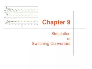
Outline We present HYDRA simulations of solid foil targets using a beam with NDCX II parameters Questions addressed: 1. Can we reach the critical point in metals such as Al with NDCX II? 2. Can we use pyrometry or VISAR measurements to distinguish between equations of state? 3. Are we at the optimum combination of pulse duration and total pulse energy?
~250TW HI beam power 1.0MJ ~14 0 Time (ns) All DT ablator Drive efficiency (%) DT/CH ablator Ablator rho-R (g cm-2) Heavy-ion direct drive LASNEX runs by John Perkins found gains ≥ 50 at 1MJ with high coupling efficiency (15%). Coupling efficiency fuel shell kinetic energy/ion beam energy 3mm solid CH shell Heavy-ion direct drive (1MJ) 50 MeV Argon Ablator 2.00mm DT fuel 1 .9mm DT gas (See Logan, Perkins, Barnard, Phys. of Plasmas, 15, 07271, 2008). Higher efficiencies and gains may be possible by using energy ramp Coupling efficiency Target gain (at 1MJ drive) Laser Indirect Drive ~ 2-4% ~ 10 Laser Direct Drive ~ 5-8% ~ 25 Heavy ion direct drive with energy ramp ~ 25% ~ 100
At 30 J/cm2 (20 kJ/g), (Al) target center reaches 1.1 eV, density 2.1 g/cc at 0.6 ns. T Density 0.6 ns T Density 1.0 ns
Evolution of center of 3.5 m thick Al foil over the heating phase (1 ns) using LEOS with maxwell construction
Evolution of center of 3.5 m thick Al foil over the heating phase (1 ns) using LEOS with maxwell construction
NDCX II will nominally operate at the Bragg peak using Lithium ions for WDM experiments Energy loss rate Li @ 0.4 MeV/amu = NDCX II (planned ) (Bragg peak) K @ 0.009 MeV/amu = NDCX I (nuclear stopping plateau) (MeV/mg cm2) (dEdX figure from L.C Northcliffe and R.F.Schilling, Nuclear Data Tables, A7, 233 (1970)) Energy/Ion mass (MeV/amu) uniformity and fractional energy loss can be high if operate at Bragg peak (Larry Grisham, PPPL) Ion beam Exit foil at energy ~0.5 x Epeak Enter foil at energy ~1.5 x Epeak
The nominal beam assumes a 30 J/cm2 2.8 MeV Li ion beam, corresponding to 20 kJ/g in Al (SRIM) HYDRA/ QEOS SRIM For HYDRA runs we assume the nominal beam results in 20 kJ/g in Al. This implies the simulated beam had a fluence of 20 J/cm2 (instead of 30 J/cm2)
Simulations show that an NDCX II double pulse experiment could confirm benefits of double pulsing 9 mm (1 ns) Ion beam 1 mm 50 Ion: Li+ or Li++ Target: Solid Ar Intensity: 30 J/cm2 (each pulse) Each pulse: 1 ns long 2nd pulse, 1ns after 1st Simulations by Siu Fai Ng (DISH; vdw EOS) (simulations by Vietzer indicate room temp Al foam also candidate)
In addition to target physics, NDCX II will serve as a platform for driver beam physics tests - RF Wobbler dynamics - beam bending - beam-plasma interactions - unneutralized acceleration with bunch compression - neutralized bunch compression and final focus Example of one module of driver:
We are proposing an ER LDRD that is relevant to Direct Drive coupling physics and NDCX II Heavy Ion Beam Approach to Inertial Fusion-Fission Hybrids (This LDRD proposal is one of two simultaneous, coordinated proposals being submitted at LLNL and LBNL) LLNL: John Barnard (PI), Alex Friedman, Wayne Meier, L. John Perkins, Ralph Moir, Michael Hay (UC Berkeley undergraduate) LBNL: Bernhard Ludewigt, Robert Budnitz, B. Grant Logan, Roger Bangerter, Andy Sessler, Per Peterson (UC Berkeley) LLNL Funding Request: FY10=375k$, FY11=375k$, FY12=375k$ LBNL Funding Request: FY10=290k$, FY11=290k$, FY12=290k$ What do the unique properties of ion beam acceleration, final focus, and ion deposition imply about ion-based fusion-fission hybrid concepts? Can low pulse energy (< ~0.5 MJ) heavy-ion-based direct drive targets be used for small entry-level hybrid (or inertial fusion energy) drivers? Can a thick liquid or wetted wall be used in a hybrid? What are the systematic tradeoffs between ion energy, ion mass, pulse energy, and target gain in hybrid systems?
We have identified a series of warm dense matter experiments that can begin on NDCX-I at Temperature < 1 eV time
NDCX II covers WDM region -- a region of large uncertainty in EOS 1020 1021 1022 1023 EOS pressure variance for 2 eqs. of state in Al (R. Lee) Density - Temperature universe 1014 1000 107 100 106 HIF eV Temperature (K) 10 105 NDCX II 1 104 Heavy-ion-beam driven warm dense matter and fusion target interactions NDCX I solid Al 0.1 103 102 1020 1021 1022 1023 1015 1040 Ion density (cm-3) From National HEDP Task Force Report, 2004.