Download
1 / 8
80 likes | 98 Views
This report details the upgrade and implementation of a GPS time synchronization system at University of Washington for neutrino detection experiments at T2K. The system includes components such as Local Time Clock Board, GPS receivers, Antennas, Rubidium Freq. Std., and more. Plans for duplicate systems at JPARC and Super-Kamiokande, redundant backups, and hot spare strategies are discussed. The To-Do list outlines FPGA code development, optical fiber interface modules design, testing procedures, and timeline for system integration and deployment.

E N D
UW report: GPS time synch system update Hans Berns and Jeff Wilkes University of Washington, Seattle T2K US-b280 meeting Sept 8, 2007 U.Wash.
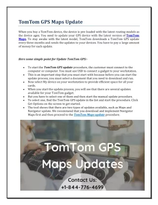
U.Wash. GPS System Block Diagram (same at both sites) All parts shown are supplied by UW { Serial TRG + Event Number SK: Local Time Clock with EventCounter+Fifo SBS 616 VME-PCI Serial Event# in (32-bit) { Event No. Spill Number T2K: Spill# out (16 bits) Spill-1 Spill Trigger(s) Spill-2 Antenna TRG + spill# out (fast serial data) Time Stamp TrueTime XL-DC GPS Rcvr. 1PPS-GPS1 Linux PC 1PPS-GPS2 VME Bus 1PPS-Ru CLK Antenna Slow Data iLotusM12M GPS Rcvr. Serial I/O or optical fiberreceiver Data-GPS1 Data-GPS2 Data-Ru Ethernet Optical Fiber Output Conv. Optical fibersto ND280 SRS FS725 Rubidium Freq. Std. 1PPS-in Serial Data 10MHz-out 100 MHz Out 1PPS Out To DAQ System 1PPS-out Required at JPARC only, for UK data system Not included our budget! Cost about 1K$
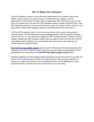
U.Wash. Custom VME Module (UW made):Local Time Clock Board • Generates timestamps from triggers + GPS data • VME 6U • 100 MHz 48-bit Clock Counter • 10 ns least count • ~32 days before rollover • 4K x 96-bit Event Fifo Buffer • Optional 512x32-bit SRAM • 5 Trigger Inputs: • 2x Spill / Event Trigger • 2x 1PPS GPS • 1x Reference/CAL (Ru. 1PPS) • 16-bit Spill Number Output (T2K) • Serial TRG/Event Number Input (for SK new electronics/TRG) • Xilinx FPGA based (Spartan-3) • Adaptable as needed • 8-bit status input flags • 8 programmable AUX/CAL outputs • For calibration & monitoring
U.Wash. Local Time Clock (V7.0) prototype module .
U.Wash. Input/output signals of the GPS system • Inputs: • 2 GPS Antenna coax cables • for primary and secondary GPS receivers • (Spill) Trigger at JPARC: NIM or TTL (decide later: easy to implement) • Secondary Trigger [optional]: NIM or TTL ( ditto ) • TRG / Event Number at Super-K: LVDS, serial format • Outputs: • 1PPS (One Pulse Per Second): NIM / TTL / optical fiber • time marker, synchronized with UTC second increment • Reference Clock: NIM / TTL / optical fiber for UK hardware • 60 MHz at Super-K • 100 MHz at T2K-280m • Delayed Trigger: NIM / optical fiber • Spill Number: 16-bit dECL (parallel) / optical fiber (serial) • Incremented after each spill trigger(optical serial format being arranged with UK ND280m group) • Ethernet: GPS DAQ data (method & formats to be discussed) • LTC counts at trigger and last 1PPS edge • GPS quality/housekeeping data (time base = 10 MHz Ru clock) (decide now…or soon? Also easy to implement)
U.Wash. System plans • Duplicate systems at JPARC and SK • primary + secondary receivers and antennae • LTC board + Rubidium clock • VME crate with Linux workstation controller and UPS • Complete duplicate backup set of parts at each site • 2 of everything on site, at both ends of neutrino beam • Decision: spare parts cold, or hot? • Run “spares” also? • Could station spares in another building, and run at all times (data to archive logfiles only) • Hot backup, remotely switchable into T2K datastream immediately in case of power failure or earthquake damage to original online hardware • Or, cold backup: leave them in storage (no burn time, brand new if/when needed) • Hans comments: probably hot is better: SK system has run for 10 years with no failures! eg, Ru oscillator has MTBF = 20 years…
U.Wash. GPS To Do List • FPGA code development for LTC • very similar for both GPS and ADC boards needed for T2K • Concentrated on ADC board development first, since it is new • New LTC board prototype v. .0 now ready • Finalize design of optical fiber interface modules • For Super-K: optical receiver for GPS signals from Radon Hut • IRIG-B data, 1PPS (1Hz) sync, slow serial data • For T2K: optical transmitter for GPS signals to ND280 DAQ • 100 MHz, 1PPS (1 Hz), spill number, spill trigger • GPS system integration & testing • Now using old-model rack receivers recovered from K2K • Test and iterate prototype LTC design (if needed) • Target finalization date: 9/30/2007 (this means: still tweaking but within e of ready to ship) • Test and debug onboard and online software • Final purchases /construction • Can wait for funds: postponable to (say) mid ’08? • Make and test full set of LTC modules (2 for each site): allow 2 months • Purchase remaining off-the-shelf commercial items for full GPS system
U.Wash. UW Task Plans/Timelines • GPS time synch system • Finalize conceptual design Done • Finalize schematics & layout designs Done • LTC prototype construction Done • Finalize FPGA logic 9/07~10/07 • LTC prototype system integration and testing 9/07~10/07 • Optical fiber module design & prototyping 9/07~11/07 • Board production 12/07~3/08 • order commercial units (when US funds available): 4/08(?) • Integrate and test system in Seattle 4/08~6/08 • Ship to Japan and install at JPARC and SK 7/08~12/08