Download
1 / 34
340 likes | 480 Views
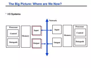
Selective Flexibility: Breaking the Rigidity of Datapath Merging. Mirjana Stojilovi ć , Institute Mihailo Pupin, University of Belgrade David Novo, É cole Polytechnique F é d é rale de Lausanne (EPFL) Lazar Saranovac, School of Electrical Engineering, University of Belgrade

E N D
Selective Flexibility: Breaking the Rigidity of Datapath Merging Mirjana Stojilović, Institute Mihailo Pupin, University of Belgrade David Novo,École Polytechnique Fédérale de Lausanne (EPFL) Lazar Saranovac, School of Electrical Engineering, University of Belgrade Philip Brisk, University of CaliforniaRiverside Paolo Ienne,École Polytechnique Fédérale de Lausanne (EPFL)
The Rigidity of Datapath Merging Datapath merging is a technique for generating a single reconfigurable datapath out of a set of input DFGs, which focuses on resource reuse among DFGs to save area. Brisk, Kaplan, and Sarrafzadeh, DAC 2004 Zuluaga and Topham, TCAD 2009
Motivation • Improve the efficiency through specialization • Area savings by merging datapaths • But what about flexibility? We want to fill this gap!
Selective Flexibility selective = the computational structures are characterized, and thus restricted, by: (1) type of operations, (2) their number, and (3) their interconnections flexibility = ability to capture and implement computational structures that are characteristic of a specific application domain
Path Fusion Creating a SUPERPATH – the (minimum area) super-sequenceof all sequences of operators found in input DFGs
Path Fusion STEP 1: Enumerate all paths from inputs to the outputs of each DFG. A path in a graph is a sequence of vertices such that from each of its vertices there is an edge to the next vertex in the sequence.
Path Fusion STEP 2: Group the paths into sets based on their length
Path Fusion STEP 3: Perform greedy search for maximum-area common subsequence (MACSeq) STEP 4: Fuse the pair of paths (sequence alignment by Needleman/Wunsch) REPEAT steps 3-4 UNTIL a single path is left in the set Brisk, Kaplan, and Sarrafzadeh, DAC 2004 A subsequence is a sequence that can be derived from another sequence by deleting some elements without changing the order of the remaining elements. Assumption: MUL > SUB > ADD
Path Fusion STEP 5: Proceed by moving the path to the set with shorter paths REPEAT steps 3-5 UNTIL a single path is left – THE SUPERPATH THE SUPERPATH
Array Generation Superpath replication to create regular array of operators. How many columns?
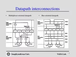
Interconnect Dimensioning Adding FPGA-like interconnections: two I/O ports per column, horizontal and vertical channels
Interconnect Dimensioning • To decide on the number of word-size tracks we do P&R • Placement: • Assign nodes to rows (top-down) • When assigning to columns: • keep distances between nodes short • emphasize graph regularity • emphasize symmetry dot, tool for laying out hierarchical drawings of directed graphs Yoon, Shrivastava, Park, Ahn, Jeyapaul, and Paek, ASP-DAC 2008 Cong and Jiang, FPGA 2008
Interconnect Dimensioning DFG to be placed (visualization by dotty)
Interconnect Dimensioning SUPERPATH Top-down greedy placement approach: Place the node in the first row with the correct operators below predecessor nodes.
Interconnect Dimensioning Placement exception: if a node is a part of a binary tree,first minimize the tree height and then place as early as possible. Rows never used are potentially removed after placement to conserve area!
Interconnect Dimensioning dotis forced to place nodes having the same rank within the same row. • dot outputs: • Vertical coordinates of nodes • Horizontal coordinates of nodes
Interconnect Dimensioning Horizontal coordinate adjustment – rounding, scaling
Interconnect Dimensioning • To decide on the number of word-size tracks we do P&R • Placement defined by dot • FPGA-like routing: • horizontal and vertical routing channels • two-IN one-OUT operators • two IN/OUT ports per column • word-size tracks (constant bitwidth) VPR, an FPGA architectural simulator and tool for P&R Betz and Rose, FPGA 2000 Ye and Rose, Transactions on VLSI systems, 2006
Interconnect Dimensioning • Inputs for VPR: • DFG Netlist • DFG Placement (dot) • Architectural description • VPRdoes the routing and reports MIN channel width to achieve legal routing
Recap Array generation Path fusion
Recap Placement Routing MIN channel width = 4 22/29
Recap Placement Routing MIN channel width = 4 23/29
Recap Placement Routing MIN channel width = 6 24/29
Recap CW1 = 4 CW2 = 4 CW3 = 6 FINAL number of rows = 12 FINAL CW = MAX{CW1, CW2, CW3} = 6
Experimental Results • Measuring area/delay with respect to ASIC and FPGA • Measuring generality Where do our domain-specific datapaths fit?
Experimental Results • 19 DFGs covering various classical signal and image processing computations (FFT, FFTr4, DCT, IDCT, FIR, IIR, autocorrelation, sobel, complex dot product, …) • DFGs extracted from applications available in EEMBC, TMS320C64x DSP library, TMS320C64x Image/Video processing library, and ExpressDFG • Loop unrolling with different factors • Groupings: • GP1 contains all DFGs, while • GP2x, GP3x and GP4x regroup DFGs into different and increasingly smaller clusters
Generality GENERALITY– the ratio of the number of successfully mapped excluded DFGs to the total number of DFGs in the group
Generality • Generality 50-90% • In most cases higher than 75% • Lower generality when the learning set is small (4B, 4D) • No extra columns in the array to potentially accommodate bigger DFGs
Area/Delay compared to ASIC and FPGA • We synthesized, placed, and routed individually all the operations found in the DFG using the gate implementations of a commercial 65nm library • Conservatively, we ignored the routing area and delay in the ASIC implementation • VPR estimates the routing area in the datapath • and the routing delay of a DFG when P&R on the datapath • Conservatively, VPRconsiders all wires as individual wires, not busses
Area/Delay compared to ASIC and FPGA Kuon and Rose, “Measuring the gap between FPGAs and ASICs”, FPGA 2006 In most cases,delay cost < 2 and area cost < 10-12 outliers outliers Conservatively, ASIC area/delay refers to a single DFG, rather than all DFGs merged
Conclusions • A novel way to merge DFGs application domain specific CGRA • A new tradeoff between generality and efficiency • Future directions: • Specialize the bitwidth of the operators • Customize the shape of the datapathto better fit the domain
Thank you. Mirjana Stojilović, mirjana.stojilovic@pupin.rs David Novo,david.novobruna@epfl.ch Lazar Saranovac, laza@el.etf.rs Philip Brisk, philip@cs.ucr.edu Paolo Ienne,paolo.ienne@epfl.ch