Download
1 / 96
960 likes | 973 Views
The SNAP Integration Model for Mechanical SC4 Breakout provides a real-time snapshot of the combined thinking for the SNAP project. It serves as a test-bed for trade studies and reveals immediate system interactions, bringing all subsystems and mission objectives into one tangible workspace.

E N D
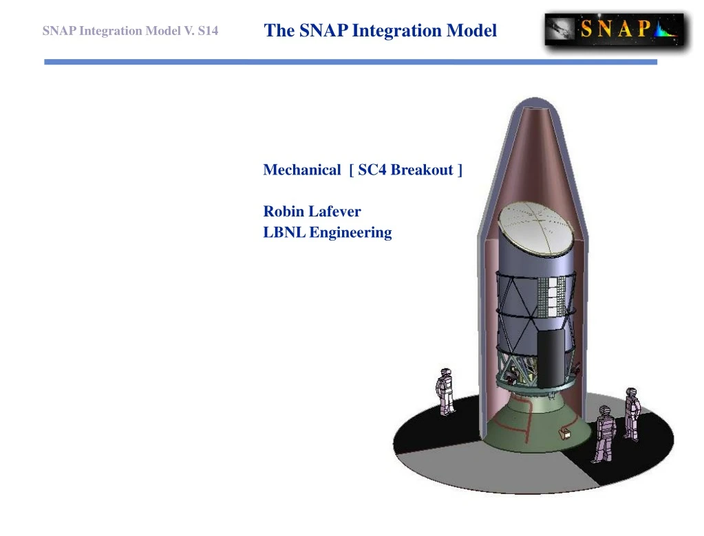
The SNAP Integration Model • Mechanical [ SC4 Breakout ] • Robin Lafever • LBNL Engineering
The Model Secondary Mirror Hexapod Bonnet Door Assembly Main Baffle Assembly Secondary Metering structure Solar Array, ‘Sun side’ Primary Mirror Optical Bench Solar Array, ‘Dark side’ Instrument Metering Structure Instrument Radiator Tertiary Mirror Instrument Bay CCD detectorsNIR detectorsSpectrographFocal Plane guiders Cryo/Particle shield Fold-Flat Mirror Spacecraft ACS CD & H Comm Power Data Solid-state recorders Shutter Hi Gain Antenna
About this Model • The current model has evolved in response to the project design flow. In its present form it • Provides a real-time snapshot of our combined thinking. • Becomes a Test-bed for detailed Trade studies. • Reveals immediate system interactions. • Brings all subsystems and mission objectives into one, tangible workspace.
How it works • Weekly Engineering meetings hosted by Pankow at SSL or Lafever at LBNL. • The Intent: • All systems are represented. • Designs and Studies are initiated, teams form, effort goes off-line. • Results from earlier studies are reported, changes adopted, production goes off-line. • “Hot” concerns get focused attention first. • The Effect: • Technical studies get tested as soon as they can be articulated. • Model updates and studies are iterated on a 1 to 3 week cycle.Detail is sacrificed for speed. • Detailed studies are iterated on a 1 to 3 week cycle and incorporated into the model. Speed is sacrificed for detail. • Multiple ‘Fitup’ models can tolerate simultaneous development. • Integration models can be assembled at any time !
System Summary • The current, model-centric view of SNAP system interfaces looks like this: • Michael Levi “The Mission” • Peter Harvey “The Process” • Dave Pankow “The Satellite” • Mike Lampton “The Telescope” • Chris Bebek “The Instrument” • Robin LafeverJohn BercovitzBobby Besuner “The Model” • Current Cross-System issues under study • Natalie RoeHenrik Van Der LippeRobin Lafever Electronics packaging/cabling • Susanna DeustuaJohn Bercovitz Stray Light and Baffling • John BercovitzRobin Lafever Shutter mechanisms • Manfred Bester Mike LeviDave Pankow Antennae and Comm
Recent Studies reflected in this model • Baffle Structure/ Metering structure: • Dave Pankow • Bobby Besuner FEA • Instrument ElectronicsPackaging • Natalie Row • Henrik Van Der Lippe • Robin Lafever • Spectrograph: • Robin Lafever • Eric Prieto • Stray Light/Baffeling: • John Bercovitz • Susanna Deustua • Mike Lampton Spacecraft: Bobby BesunerDave Pankow Robin Lafever Michael Levi • Focal Plane Assembly: • Chris Bebek • John Bercovitz • Robin Lafever • Shutter Assembly: • Chris Bebek • John Bercovitz • Mike Lampton • Michael Levi • Robin Lafever Optical /Thermal Mounts: Mike Lampton Robin Lafever Dave Pankow
Deliverables • The ModelsThe Assembly presented here, along with tooling, fiducials, and variations are available as 3d CAD models, and can be exported in a variety of formats. (earlier studies have been carried to NASA-IMDC and back, for example)FEA models are also available • The GraphicsScreen shots, and Hi-res graphics are packaged as Web-available files in a variety of formats that feed directly into ongoing presentations, such as this one. • Engineering modelsLow cost study models are already in the worksMock-ups and study models, and exemplars exist alreadyAnd, John Bercovitz and Chris Bebek have examples of the REAL thing ! A “get yer hands in it !” scale mockup of the Optical Bench, andRapid Prototype detail models are being developed right now.
Appendix • Model Overview Cut 1 • Model Overview Cut 2 • Doors • Telescope • Optical Bench • Instrument Bay Optics • Instrument Detail • Current Instrument Model • Current Focal Plane Model • Optics • Reflex Mirror Test set-up • Reflex Inverted • Reflex Mirror Cut-away A • Reflex Mirror Cut-away B • Packaging Cutaway • Satellite Peel-away 01 • Satellite Peel-away 02 • Exploded View • Moving Parts The collections of graphics in this appendix have been formatted and sequenced so they are ready to paste into other presentations for this Review. Captions have been kept to a minimum to avoid excessive editing by the user. Raw graphics are also available at: http://www-eng.lbl.gov/~lafever/SNAP/Snap_14/S14_Workup/AAAA.html
Model Overview Cut 1 • Door and Main Baffle Assembly
Model Overview Cut 1 • Primary Interior Baffling
Model Overview Cut 1 • Body-mounted Solar Arrays Dark side Sun side
Model Overview Cut 1 • Optical Telescope Assembly in the • SNAP observatory
Model Overview Cut 1 • Integrated OTA and Instrument package
Model Overview Cut 1 • Integrated OTA and Instrument package
Model Overview Cut 1 • Integrated OTA and Instrument package
Model Overview Cut 1 • Spectrograph and Instrument detector assembly
Doors • Door opening sequence
Packaging Cutaway • Satellite in launch configuration • ( MLI not shown )
Packaging Cutaway • Interior structure and packaging
Current Focal Plane Model Filter Array Detector Array PC back end electronics Incoming, Science light Transition light “Dark Inner Cone” Shutter Assembly Spectrograph
Current Instrument Model Radiator Back-end electronics Thermal Links CCD / HgCdTl detector array Spectrograph Filter array Shutter Cryo/Particle/Light shield Cold Plate Near elactronics
Satellite Peel-away 01 • Interior cutaway