Download
1 / 16
160 likes | 171 Views
This lecture reviews digital circuits, Boolean functions and expressions, logic gates, decoders, encoders, and multiplexors.

E N D
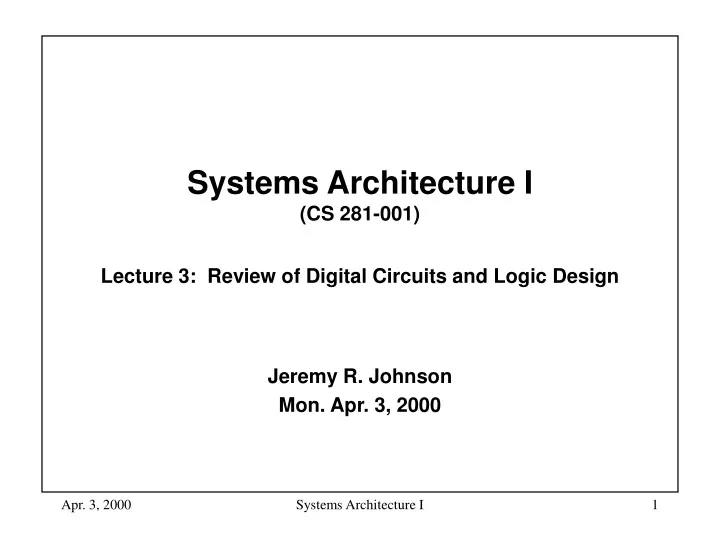
Systems Architecture I (CS 281-001)Lecture 3: Review of Digital Circuits and Logic Design Jeremy R. Johnson Mon. Apr. 3, 2000 Systems Architecture I
Introduction • Objective: To understand how the simple model computer from the previous lecture could be implemented using logic gates. • Review of Boolean functions and expressions • Review of logic gates • Decoders, Encoders, and Multiplexors References: Dewdney, The New Turing Omnibus (Chapter 3, 13, and 28) and Sec. B1-B3 of the text. Systems Architecture I
x0 f x1 s Boolean Functions • A boolean variable has two possible values (true/false) (1/0). • A boolean function has a number of boolean input variables and has a boolean valued output. • A boolean function can be described using a truth table • There are 22n boolean function of n variables. s x0 x1 f 0 0 0 0 0 0 1 0 0 1 0 1 0 1 1 1 1 0 0 0 1 0 1 1 1 1 0 0 1 1 1 1 Multiplexor function Systems Architecture I
Boolean Expressions • An expression built up from variables, and, or, and not. x y x y 0 0 0 0 1 0 1 0 0 1 1 1 x y x + y 0 0 0 0 1 1 1 0 1 1 1 1 x x 0 1 1 0 and or not Systems Architecture I
Boolean Expressions • A boolean expression is a boolean function. • Any boolean function can be written as a boolean expression • Disjunctive normal form (sums of products) • For each row in the truth table where the output is true, write a product such that the corresponding input is the only input combination that is true • Not unique • E.G. (multiplexor function) s x0 x1 + s x0 x1 + s x0 x1 + s x0 x1 s x0 x1 f 0 0 0 0 0 0 1 0 0 1 0 1 0 1 1 1 1 0 0 0 1 0 1 1 1 1 0 0 1 1 1 1 Systems Architecture I
Boolean Logic • Boolean expressions can be simplified using rules of boolean logic • Identity law: A + 0 = A and A 1 = A. • Zero and One laws: A + 1 = 1 and A 0 = 0. • Inverse laws: A + A = 1 and A A = 0. • Commutative laws: A + B = B + A and A B = B A. • Associative laws: A + (B + C) = (A + B) + C and A (B C) = (A B) C. • Distributive laws: A (B + C) = (A B) + (A C) and A + (B C) = (A + B) (A + C) • Demorgan’s laws: A + B = A B and A B = A + B • The reason for simplifying is to obtain shorter expressions, which we will see leads to simpler logic circuits. Systems Architecture I
Simplification of Boolean Expressions • Simplifying multiplexor expression using Boolean algebra s x0 x1 + s x0 x1 + s x0 x1 + s x0 x1 = s x0 x1 + s x0 x1 + s x1 x0 + s x1 x0 (commutative law) = s x0 (x1 + x1)+ s x1 (x0 + x0)(distributive law) = s x0 1+ s x1 1 (inverse law) = s x0+ s x1 (identity law) • Verify that the boolean function corresponding to this expression as the same truth table as the original function. Systems Architecture I
Logic Circuits • A single line labeled x is a logic circuit. One end is the input and the other is the output. If A and B are logic circuits so are: • and gate • or gate • inverter (not) A B A B A Systems Architecture I
x0 x1 s Logic Circuits • Given a boolean expression it is easy to write down the corresponding logic circuit • Here is the circuit for the original multiplexor expression Systems Architecture I
Logic Circuits • Here is the circuit for the simplified multiplexor expression x0 x1 s Systems Architecture I
Nand Gates • A nand gate is an inverted and gate • All boolean functions can be implemented using nand gates(and and not can be implemented using nand) x y x | y 0 0 1 0 1 1 1 0 1 1 1 0 nand x = x x Systems Architecture I
Decoder • A decoder is a logic circuit that has n inputs (think of this as a binary number) and 2n outputs. The output corresponding to the binary input is set to 1 and all other outputs are set to 0. d0 b0 d1 b1 d2 d3 Systems Architecture I
Encoder • An encoder is the opposite of a decoder. It is a logic circuit that has 2n inputs and n outputs. The output equal to the input line (in binary) that is set to 1 is set to 1. d0 d1 b0 d2 b1 d3 Systems Architecture I
Multiplexer • A multiplexor is a switch which routes n inputs to one output. The input is selected using a decoder. d0 d1 d2 d3 s1 s0 Systems Architecture I
Implementing Logic Gates with Transitors +V +V A NAND B A output B gate ground ground A Transistor NOT Gate A Transistor NAND Gate Systems Architecture I
Exercises • Prove De Morgan’s laws. • Conjunctive normal form consists of products of sums. Obtain a conjunctive normal form for the multiplexer on slide 5 and draw the corresponding circuit. How does the number of gates compare with the circuit on slide 9. • Design a 3 8 decoder. • Design an 8 3 encoder. • Redesign the multiplexer on slide 14 using only inverters, three-input NAND gates, and a single four-input NAND gate. • Show a transistor NOR gate Systems Architecture I