Download
1 / 35
360 likes | 703 Views
This project focuses on creating a cost-effective power inverter that efficiently converts 12VDC to 120VAC, producing a pure sinusoidal waveform. The design includes a switch-mode power supply with key components like PWM control circuit, half-bridge converter, transformer, and low-pass filter to achieve a continuous 300W output. The presentation outlines the challenges faced, solutions implemented, component choices, and testing results, showcasing the journey from design to prototype. Future goals include refining the design for better cost-effectiveness and performance.

E N D
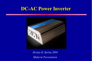
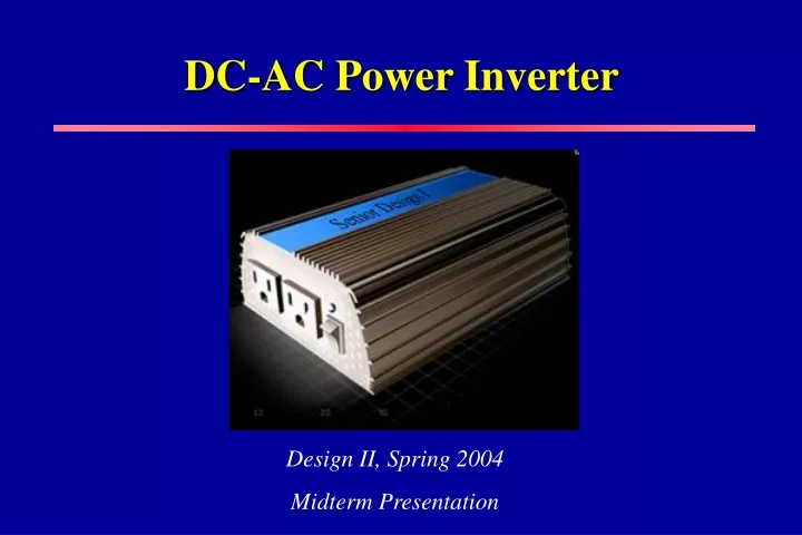
DC-AC Power Inverter Design II, Spring 2004 Midterm Presentation
Team Members Min-Chiat Wee Team Leader Daniel Martin Faculty Advisor Dr. Yaroslav Koshka Dustin Bailey Industrial Advisor: Dr. Mark Kinsler Jason Horner
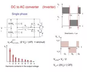
Abstract • Design a switch-mode power supply that converts 12 VDC to 120 VAC • Pure sinusoidal waveform with 60 Hz frequency • 300 W continuous output
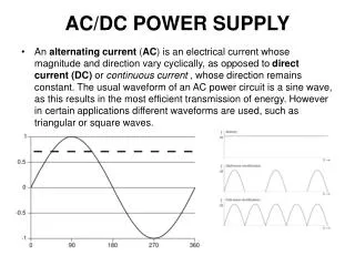
Problem Statement • Problems: • Inexpensive inverters are very inefficient due to a high harmonic content of the output signal • Pure sine wave inverters have a high cost per watt ratio • Solution: • An inexpensive inverter that produces a near perfect sine wave output
Main Components 12 VDC Input (from vehicle battery) PWM Control Circuit Half-bridge Converter Transformer Low-pass Filter Full-bridge Inverter Sinusoidal PWM Controller 120 VAC, 60 Hz, 300 W Output
PWM Control Circuit 12 VDC Input (from vehicle battery) PWM Control Circuit Half-bridge Converter Transformer Low-pass Filter Full-bridge Inverter Sinusoidal PWM Controller 120 VAC, 60 Hz, 300 W Output
PWM Controller • Produces two complementary pulses to control half-bridge transistors • Problem: • Voltage dropped less than 170VDC when the input voltage was decreased • Solution: • A feedback network was added for voltage regulation
PWM Oscilloscope Waveform Prototype Device as Built
Half-bridge Converter 12 VDC Input (from vehicle battery) PWM Control Circuit Half-bridge Converter Transformer Low-pass Filter Full-bridge Inverter Sinusoidal PWM Controller 120 VAC, 60 Hz, 300 W Output
Half-bridge Converter • Chops the 12 VDC to produce a 12 V, 100 kHz, square pulse • Problem: • IRF740A MOSFETs has an Rds(on) = 0.55Ω, resulting in high power losses. • Solution: • Chose IRF530 MOSFETs with an Rds(on) = 0.16 Ω
Half-bridge Oscilloscope Readings Prototype Device As Built
Transformer 12 VDC Input (from vehicle battery) PWM Control Circuit Half-bridge Converter Transformer Low-pass Filter Full-bridge Inverter Sinusoidal PWM Controller 120 VAC, 60 Hz, 300 W Output
Step Up Transformer • Steps up voltage from 12 VAC to 340 VAC • Problem: • Initial transformer had high internal capacitance leading to failure of device • Solution: • Custom ordered a transformer to fit our design constraints
DC-DC Converter Testing Device As Built Simulation
Sinusoidal PWM Controller 12 VDC Input (from vehicle battery) PWM Control Circuit Half-bridge Converter Transformer Low-pass Filter Full-bridge Inverter Sinusoidal PWM Controller 120 VAC, 60 Hz, 300 W Output
Sinusoidal PWM Circuit • Last Semester: • PIC18F452 – too many unused ports • Insufficient dead-time in PIC program caused cross-conduction in full-bridge inverter • This Semester: • Chose PIC18F252 – fewer unused ports • Programmed 500ns between each control pulse
Initialize all variables Count0 = 300 (300 duty cycles) 300 duty cycle values? One Sampling Period? Output 1 = high, Output 2 = low Read duty cycle table (increment pointer) Duty cycle and sampling period timer Output 1 = low, Output 2 = high Decrement Count0 by 1 Has duty cycle been reached? Software Flow Diagram yes no no yes no yes
Sinusoidal PWM Drive Pulses Device As Built Simulation
Full-bridge Inverter 12 VDC Input (from vehicle battery) PWM Control Circuit Half-bridge Converter Transformer Low-pass Filter Full-bridge Inverter Sinusoidal PWM Controller 120 VAC, 60 Hz, 300 W Output
Full-bridge Inverter • Converts 170 VDC to a 120 Vrms, 60 Hz, sine wave • IRF740A MOSFETs • Vdss = 400 V • Id = 10 A • Rds(on) = 0.55 Ω
Simulation vs. Actual (unfiltered) Simulation Device As Built
60 Hz 60 Hz 18 kHz 18 kHz Frequency Spectrum Before Filtering Simulation Device As Built
Low-pass Filter 12 VDC Input (from vehicle battery) PWM Control Circuit Half-bridge Converter Transformer Low-pass Filter Full-bridge Inverter Sinusoidal PWM Controller 120 VAC, 60 Hz, 300 W Output
Low-pass Filter • 2nd order L-C filter • Filters to retain a 60 Hz fundamental frequency • Few components • Handle current • Wind inductor (fine tune)
Final Output Testing Simulation Prototype
Frequency Spectrum After Filtering Simulation Device As Built
PCB Layout Dimensions: 7.5” x 6.5” x 2.5”
Status and Goals • Continue working with PCB • Fine tune filter • Improve packaged appearance • Attempt to further reduce costs
Acknowledgements • Dr. Yaraslov Koshka • Dr. Mark Kinsler • Dr. Mike Mazzola • Dr. Raymond Winton • Dr. Herb Ginn • Jim Gafford • Robin Kelley • Len Cox • Jessie Thomas
Any Questions? ???