Download

1 / 12
140 likes | 423 Views
Negative Feedback. Negative feedback is one of the most useful concepts in electronic circuits, particularly ) op-amp applications. Negative feedback is the process whereby a portion of the out- voltage of an amplifier is returned to the input with a phase angle that opposes the input signal.

E N D
Negative Feedback Negative feedback is one of the most useful concepts in electronic circuits, particularly ) op-amp applications. Negative feedback is the process whereby a portion of the out- voltage of an amplifier is returned to the input with a phase angle that opposes the input signal.
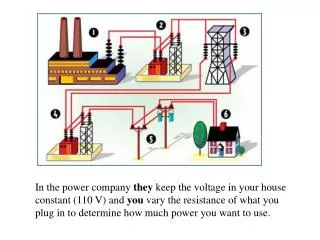
Why Negative Feedback? • An amplifier cannot give an output that has a voltage greater its supply voltage. • If the gain of the amp is 20,000, the supply is 12Volts and the input voltage is 2 Volts then the output is calculated as 20,000 * 2 = 40,000Volts. • Obviously 40,000Volts is just not practical and the output will go as high as it can and stay at 12 volts. • Negative feedback reduces the gain and increases the bandwidth.
Calculating the gain with feed backfor noninverting configuration
Calculating the gain with feed backfor noninverting configuration • Recall that AOL is the open loop gain i.e. gain without feed back. • VOUT=AOL(VIN - Vi) • Recall that Vi= (Vout / Rf+Ri)* Ri • Let Ri /(Ri+ Rf)= B, • Then apply basic algebra as follows: • Vout = AolVin -AolBVout • Vout + AolBVout = AolVin • Vout(1 + AolB) = AolVin • Since the total voltage gain of the amplifier in the previous slide is Vout/Vin
Calculating the gain with feed backfor noninverting configuration • The product of AolBis typically much greater than 1 hence, Becomes, The above formula gives the gain of a noninverting amplifier.
Non-inverting Amplifier: Example • Problem: Determine the output voltage and current for the given non-inverting amplifier. • Given Data: R1= 3kW, R2 = 43kW, vs= +0.1 V • Assumptions: Ideal op amp • Analysis: Since i-=0,
Inverting Amplifier • Let's say a current of 1 milliamp is caused to flow to the inverting input pin through a 1000 ohm input resistor, Ri, the Op-Amp tries to maintain equilibrium, i.e., no current flow in that inverting input pin (high resistance). To do this marvelous feat, it generates an output voltage of the opposite polarity, which maintains that 1 milliamp to flow through a 10 K feedback resistor, Rf. Because the feedback resistor is ten times the value of the input resistor, it will require ten times the voltage to cause that same 1 mA to flow. • The view from the input pin: there is a current of 1 milliamp coming down the input resistor, and at the same time AND there is a current of 1 milliamp coming from the feedback resistor. There is no current left over for the input pin; • This satisfying the zero current requirement of the Op-Amp. This is because the output is the inverse of the input and both waves cancel. • This the zero current results in zero voltage at the inverting input terminal and is referred to as virtual ground. This condition is illustrated in the next slide.
Inverting Amplifier Because Iin and If are the same but opposite, the voltage at the inverting input must be 0. • Since there is zero current flowing to the inverting input, the current through Ri is therefore equal but opposite to Rf. • => If = -Ii • The voltage across Ri=-Vin because of the virtual ground on the other side of the resistor. i.e. 0 – Vin = - Vin • Iin = - Vin/Ri The voltage across Rf = Vout because of the virtual ground. i.e. Vout – 0= Vout => If= Vout/Rf
Inverting Amplifier • Recall that there is zero current flowing to the inverting input, the current through Ri is therefore equal but opposite to Rf. • => If =-Ii • Vout/Rf = - Vin/Ri • => Vout/Vin = - Rf/Ri • This final equation gives the gain for an inverting amplifier. The minus sign implies that the output is inverted. • Recall from previous slide that gain is Vout/Vin