Download
1 / 28
410 likes | 1.79k Views
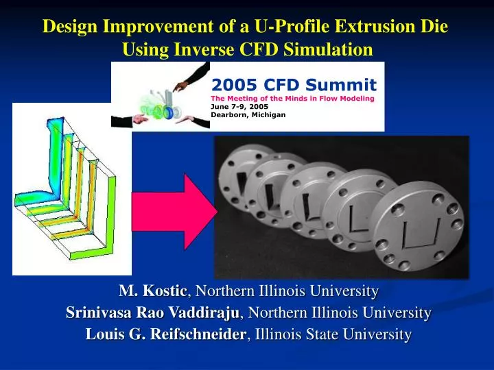
2005 CFD Summit The Meeting of the Minds in Flow Modeling June 7-9, 2005 Dearborn, Michigan. Design Improvement of a U-Profile Extrusion Die Using Inverse CFD Simulation. M. Kostic , Northern Illinois University Srinivasa Rao Vaddiraju , Northern Illinois University

E N D
2005 CFD SummitThe Meeting of the Minds in Flow ModelingJune 7-9, 2005Dearborn, Michigan Design Improvement of a U-Profile Extrusion Die Using Inverse CFD Simulation M. Kostic, Northern Illinois University Srinivasa Rao Vaddiraju, Northern Illinois University Louis G. Reifschneider, Illinois State University
Motivation and Objectives • To design and fabricate a U-profile die for testing using a laboratory extruder • To assess the role of CFD simulation for extrusion die design • (1) die swell • (2) mass flow balance, and • (3) optimum die profile-shape • How the simulation results compare to actual experimental results • To assess the role of the calibrator in shaping the final profile of the extrudate • Cooling simulation in the calibrator using the experimental data
The flow is steady and incompressible Polyflow Inverse Extrusion SimulationGeneral Assumptions : Body forces and Inertia effects are negligible in comparison with viscous and pressure forces. Specific heat at constant pressure, Cp, andthermal conductivity, k, are assumed constant
27.94 mm 25.4 mm (2.54 mm thick) Required Extrudate Profile
h ( T ) & h g = 0 ( T , ) , where - 1 n & h g æ ö ( T ) + 1 0 ç ÷ t * è ø é ù - A ( T D ) h = - 1 2 ( T ) D exp ê ú 0 1 + - A ( T D ) ë û 2 2 Viscosity Model: Cross-WLF HIPS: DOW Styron 478 (MFI=6) BASF 496N (MFI=2.8) Pseudoplacticity included Viscoelastic effects neglected.
Extruder Die Mounting Plate Extruder U-Profile Adapter Plate Transition Plate Exploded View of Die Assembly Melt Flow direction Simulation determines Pre-Land & Die Land plates Pre-Land Die Land
MESH 16,592 hex. elem. 19,530 nodes. Solution Windows PC, 1 GB RAM, @ 2.39 GHz, Isothermal analysis required 552 minutes CPU. Finite Element Mesh
Pre-land inlet geometry fixed Die land: uniform passage Free surface exit matches target extrudate: fixed Boundary Conditions (symmetry) No slip at die surface Inlet: fully developed flow Free Surface: Zero traction & No normal velocity Symmetry Plane Exit: Zero normal stress & Plug flow
Profile of the inlet to the pre-land plate was determined by a series of trial and error extrusion simulations to insure a balanced mass flow exiting the die. Outlet 1 Outlet 2 Outlet 3 Outlet 4 Outlet 5 Outlet 7 Outlet 6 Flow simulation only within the die
Pressure (Pa) Velocity Magnitude (m/s) Representative Pressure and Velocity Results
Die Land Pre-land Inlet Pre-land Inlet Die Land Inverse Extrusion simulation results with Pre-land and Die Land Contours Extrudate Free Surface (Target Profile) Symmetry Plane (Target Profile)
Direct Extrusion simulation result with Styron 478 and Styron 496 478 direct extrusion extrudate profile 496 direct extrusion extrudate profile Target extrudate profile As expected the free surface outlet profile from the results of direct extrusion with Styron 478 is very close to the target profile we used in inverse extrusion CFD simulation.
Vacuum Lines Extrudate Passage Cooling Lines Stacked Plate Design: Passage matches target profile, no taper along flow direction. Vacuum Lines Vacuum Calibrator Design
Cut Off Cooling Tank Schematic of U-Profile Extrusion Line with Data Acquisition Inlet IR Upper T/C Upper Exit IR Upper Calibrator Puller U-Profile Die Lower Calibrator Puller Lower Exit IR Lower T/C Product
Calibrator Set-up (opened) Inlet IR Exit Top IR Die Exit Bottom IR Cooling Tank
CalibratorExit Inlet Die Exit Bottom IR
Corner pulling away Side wall shrinkage: 3% – 6% Air gap = shrinkage Product Shrinkage at Calibrator Exit
Calibrated mass balance E G C A I Calibration rearranges mass balance Air cushion mass balance P@3 kg/hr (most uniform thickness) is 6% thinner than target: draw down and shrinkage affects.
Fredette Order of magnitude difference: can testing results be generalized? HeatTransferData Temperature data input to transient 1-D simulation to iterate for effective heat transfer between extrudate and calibrator.
Boundary Conditions for Extrudate Cooling Simulation Free Surface L = 50 mm + h h = h conv tot rad Tinlet = 505 K = 10 W/m2K + 15 W/m2K T = 295 K Calibrator L = 95 mm 2 = 303 K h = 175 W/m K, T upper 2 h = 225 W/m K, T = 297 K lower h upper h low er V = 6.3 mm/s Adiabatic Adiabatic
Evolution of Temperature Contours as Extrudate Passes Through Calibrator 150 - 200 • Temperature History Plot Points • Upper • Middle • Lower 200+ 150 - 200 100 - 150 100 - 150 50 - 100 Black area solidified Inlet Outline of full profile shown Midway < 50 Exit
Conclusions • Inverse extrusion simulation predicts profile die shape • Custom tuning of profile dies still required. • Total product design requires coupled design of the die and the calibrator, however… • Calibration design difficult due to coupled heat transfer and product deformation • difficult to gather general empirical data, • difficult to simulate due to contact element boundary conditions.
ACKNOWLEDGEMENTS • Dr. M. Kostic and S. R. Vaddiraju thank: • NICADD (Northern Illinois Centre for Accelerator and Detector Development), NIU • Fermi National Accelerator Laboratory, Batavia, IL • NIU’s College of Engineering and Department of Mechanical Engineering • Dr. L. Reifschneider thanks: • College of Applied Science and Technology at Illinois State University for financial support to conduct the die design research.
Contact Information: mailto: kostic@niu.edu www.kostic.niu.edu mailto: vaddirajs@yahoo.com www.vaddiraju.com mailto: lgreifs@ilstu.edu