Download
1 / 26
270 likes | 455 Views
Performance of Discrete Wavelet Transform – Artificial Neural Network Based Signal Detector/Equalizer for Digital Pulse Interval Modulation in Practical Indoor Optical Wireless Links. Z. Ghassemlooy, S. Rajbhandari and M. Angelova School of Computing, Engineering & Information Sciences,

E N D
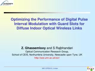
Performance of Discrete Wavelet Transform – Artificial Neural Network Based Signal Detector/Equalizer for Digital Pulse Interval Modulation in Practical Indoor Optical Wireless Links Z. Ghassemlooy, S. Rajbhandari and M. Angelova School of Computing, Engineering & Information Sciences, University of Northumbria, Newcastle upon Tyne, UK http://soe.unn.ac.uk/ocr/
Outline • Optical wireless – introduction • Modulation Techniques- Overview • Mutipath induces ISI • Unequalized power penalty • Wavelet-ANN receiver • Final comments
What Optical Wireless Offers ? • Abundance bandwidth • Free from electromagnetic interference • High data rate • No multipath fading • High Directivity. • Secure data transmission • Spatial confinement. • Low cost of deployment • License free operation • Quick to deploy • Compatible with optical fibre • Simple transceiver design. • Small size, low cost component and low power consumptions.
Modulation Techniques • On-off keying (OOK): the most basic, simple to implement but requires a high average optical power. • Pulse position modulation (PPM): The most power efficient but require high bandwidth, susceptible to the multipath induced intersymbol interference (ISI). • Differential PPM (DPPM) and digital pulse interval modulation (DPIM): Variable symbol length, built-in symbol synchronization; improved throughputs and efficient utilization of the available bandwidth compared to PPM. • Dual header pulse interval modulation (DH-PIM): Variable symbol length , built-in symbol synchronization; the most efficient utilization of channel capacity compared to OOK, PPM and DPIM.
20 18 16 14 12 Normalized bandwidth requirement 10 PPM 8 DH-PIM1 6 DPIM DH-PIM2 4 2 OOK 0 2 3 4 5 6 7 8 Bit resolution, M 0 -2 DPIM -4 -6 DH-PIM2 DH-PIM1 Normalized Power Requirement (dB) -8 PPM -10 -12 -14 -16 2 3 4 5 6 7 8 Bit Resolution, M Normalized Power and Bandwidth Requirement • PPM the most power efficient • while requires the largest • bandwidth. • DH-PIM2is the most bandwidth efficient. • DH-PIM and DPIM shows almost identical bandwidth requirement and power requirement. • There is always a trade-off • between power and bandwidth.
Indoor Optical Wireless Links • The key issues are: • The eye safety • shift to a higher wavelength of 1550 nm where the eye retina is less sensitive to optical radiation • power efficient modulation techniques. • Mobility and blocking • Use diffuse configuration instead of line of sight, but at cost of • reduced data rate • increased path loss • multipath induced inter-symbol-interference (ISI) • High noise at receiver due toartificial light.
Effect of Artificial Light • Dominant noise source at low data rate. • Interference produce by fluorescent lamp driven by electronic ballasts can cause serious performance degradation at low data rate. • The effect of artificial light is minimised at the receiver using combination of the optical band pass filter and electrical low pass filter. • At the high data rate, the ISI is the limiting factor in the performance of the system instead of artificial light.2 1Figure : Optical power spectra of common ambient infrared sources. Spectra have been scaled to have the same maximum value. 1J. M. Kahn and J. R. Barry, Proceedings of IEEE, vol. 85, pp. 265-298, 1997. 2A. J. C. Moreira, R. T. Valadas, and A. M. d. O. Duarte, IEE Proceedings -Optoelectronics, vol. 143, pp. 339-346, 1996.
LOS Diffuse Received signal for non-LOS Links 1.2 Diffuse shadowed 1 0.8 LOS shadowed 0.6 Amplitude 0.4 0.2 0 -0.2 -0.4 0 2 4 6 8 10 Normalized Time Intersymbol Interference (ISI) • Limiting factor in achieving high data rate in diffuse links. • ISI is due to broadening of pulse. • Diffuse links are characterised by RMS delay spread. • The impulse response in Ceiling bounce model is given by1 : where u(t) is the unit step function 1- J. B. Carruthers and J. M. Kahn, IEEE Transaction on Communication, vol. 45, pp. 1260-1268, 1997.
Unequalized Performance • The discrete-time impulse response of the cascaded system is • In non-LOS links, ck contains a zero tap, a single precursor tap (with the largest magnitude) and possibly multiple postcursor taps. • The optimum sampling point is at the end of each slot period Ts for LOS link. • On dispersive channels, the optimum sampling point changes as the severity of ISI changes.
Unequalized Performance • For the LOS channel, the slot error probability Pse of DPIM is given by: where R is the photodetector responsivity, η is the noise spectral density, Pavg is the average transmitted optical signal power, Rb is the bit rate, M is bit resolution and L = 2M. • In a multipath channel, the Pseis calculated by summing the error probabilities in all possible sequences. where bi is the m-slot DPIM(NGB) sequence and . where optis the optimum threshold level, set to the midway value of RPave (Tb)0.5
Unequalized Power Penalty • There is exponential growth in power penalty with increasing delay spread for all orders of DPIM. • The average optical power required to achieve a desirable error performance is impractical for normalized delay spread grater than 0.1. • To mitigate the ISI the solution is to incorporate an equalizer at the receiver .
Equalization • Maximum likelihood sequence detector : Though the optimum solution, not suitable for variable symbol length modulation schemes like DPIM since symbol boundaries are not known. • Hence sub-optimum solutions based on finite impulse response filters would be the preferred option. • But equalization based on the finite impulse response (FIR) filter suffers from severe performance degradation in time varying and non-linear channels.1 • The equalization problem can be formulated as classification problem and hence artificial neural network can be used to reduce the effect of ISI.2,3 1- A. Hussain, J. J. Soraghan, and T. S. Durrani, IEEE Transactions on Communications, vol. 45, pp. 1358-1362, 1997. 2- J. C. Patra and N. R. N. Pal, Signal Processing, vol. 43, pp. 81 - 195, 1995. 3- L. Hanzo, C. H. Wong, and M. S. Yee, Adaptive wireless transceivers: Wiley-IEEE Press, 2002, pp. 299-383.
Equalization: A Classification Problem • Classification capability of FIR filter equalizer is limited to a linear decision boundary, which is a non-optimum classification strategy1. • FIR base equalizers suffer from severe performance degradation in time varying and non-linear channel2. • The optimum strategy would be to have a nonlinear decision boundary for classification. • ANN is employed for equalization because of its capability to form complex nonlinear decision regions. - In fact both the linear and DFE are a class of ANN3 . • Wavelet based equalization4. 1- L.Hanzo, et al, Adaptive wireless transceivers: Wiley-IEEE Press, 2002, pp. 299-383. 2- C. Ching-Haur, et al , Signal Processing,vol. 47, no. 2, pp. 145 - 158 1995. 3- S. Haykin, Communications Magazine, IEEE , vol.38, no.12, pp. 106-114, Dec. 2000 4- D. Cariolaro et al, IEEE Intern. Conf. on Communications, New York, NY, USA, pp. 74-78, 2000.
Block Diagram of Receiver Based on Classification Optical Signal Optical Receiver Feature Extraction Pattern Classification Post-Processing Wavelet Transform Neural Network • For efficient classification, feature extraction tools are incorporated in the receiver. • The receiver is made modular by having separate block for : (a) Feature extraction (wavelet transform) and (b) pattern classification (ANN). • WT-ANN based receiver outperforms the traditional equalizers1. 1- R. J. Dickenson and Z. Ghassemlooy, International Journal of Communications Systems, Vol. 18, No. 3, pp. 247-266, 2005.
Feature Extraction Tools Time-Frequencies Mapping Wavelet Transform Fourier Transform Short-Time Fourier Transform No time-frequency Localization Fixed time-frequency resolution: Uncertainty problem No resolution problem :Ultimate Transform
CWT vs. DWT • Infinite scale in CWT, having highly redundant coefficients. • Redundancy in CWT can be removed by utilizing the DWT. • The DWT is easier to implement using filter bank of high pass and low pass filters. • Reduced computational time compared CWT. • Possibility of denoising of signal by thresholding the wavelet coefficient in DWT.
Discrete Wavelet Transform 2 2 2 2 Level 1 DWT coefficients Level 2 DWT coefficients Down- sampling • DWT coefficient can efficiently be obtained by successive filtering and down sampling. • Signal is decomposed using high pass h[n] and a low pass g[n] filters and down sampled by 2. • The two filter are related to each other and are known as a quadrature mirror filter. Filtering cD1 cD2 h[n] Signal h[n] cA1 x[n] cA2 . . . g[n] g[n]
Denoising Signal using DWT • Denoising is performed by hard/soft thresholding of the detail coefficients. - Hard thresholding - Soft thresholding - The threshold level for universal threshold scheme : :the variance of the wavelet coefficient. • Denoised signal where is the inverse WT .
WT-ANN Based Receiver Model • The receiver incorporates a feature extractor (DWT) and a pattern classifier (ANN). • 16-samples per bit. • Signal is decimated into W-bits discrete sliding window. (i.e. each window contains a total of 16W discrete samples ). • Information content of the window is changed by one bit. • 3-level DWT of each window is calculated. • DWT coefficients are denoised by: a) Thresholding : A threshold is set and ‘soft’ or ‘hard’ thresholding are used for detail coefficients. b) Discarding coefficients: detail coefficients are completely discarded. • The denoised coefficient are fed to ANN. • ANN is trained to classify signal into two binary classed based on the DWT coefficients.
Results • Unequalized DPIM- worst error performance. • The unequalized error performance is not practically acceptable for highly diffuse channel like channels with Drms > 5ns. • Both linear and DWT-ANN equalizers show improve error performance compared to unequalized cases. • The DWT-ANN based receiver showed a significant improvement in SER performance compared to linear equalizer. • The SNR gain with DWT-ANN at the SER of 10-5 is ~ 8.6 dB compared to linear equalizer. • Performance of DWT-ANN also depends on selection of mother wavelet, with discrete Meyer wavelet showing the best performance. • Further improvement in SER performance can be achieved by using error control coding. Figure : The SER performance against the SNR for unequalized, Linearly equalized and a DWT-ANN based receiver at data rate of 200 Mbps for diffuse links with Drms of 1, 5 and 10 ns.
Conclusions • The traditional tool for signal detection and equalization is inadequate in time-varying non-linear channel. • Digital signal detection can be reformulated as feature extraction and pattern classification. • Both discrete and continuous wavelet transform is used for feature extraction. • ANN is trained for classify received signal into binary classes. • DWT-ANN equalizers performance offers an SNR gain of almost 8 dB at SER of 10-5 at data rate of 200 Mbps for all values of channel delay spread. • The rapid increase in the processing time of electronic devices can make the system practically feasible. • Practical implementation of the proposed system in the process of being carried out at the photonics Lab, Northumbria University.
Acknowledgement • Northumbria University for supporting the research. • OCRG and IML lab for providing require software for simulation.
Thank you! Questions/Suggestions/Comments