Download
1 / 62
640 likes | 713 Views
Learn about the frequency domain analysis of CT and DT LTI systems, including responses to various input signals like sinusoidal, complex exponential, and periodic inputs. Understand how to analyze output signals and frequency responses using Fourier transforms.

E N D
CT, LTI Systems • Consider the following CT LTI system: • Assumption: the impulse response h(t) is absolutely integrable, i.e., (this has to do with system stability (ECE 352))
Response of a CT, LTI System to a Sinusoidal Input • What’s the response y(t) of this system to the input signal • We start by looking for the response yc(t) of the same system to
Response of a CT, LTI System to a Complex Exponential Input • The output is obtained through convolution as
The Frequency Response of a CT, LTI System is thefrequency response of the CT, LTI system = Fourier transform of h(t) • By defining it is • Therefore, the response of the LTI system to a complex exponential is another complex exponential with the same frequency
Analyzing the Output Signal yc(t) • Since is in general a complex quantity, we can write output signal’s phase output signal’s magnitude
Response of a CT, LTI System to a Sinusoidal Input • With Euler’s formulas we can express as and, by exploiting linearity, it is
Response of a CT, LTI System to a Sinusoidal Input – Cont’d • Thus, the response to is which is also a sinusoid with the same frequency but with the amplitudescaled by the factor and with the phase shifted by amount
DT, LTI Systems • Consider the following DT, LTI system: • The I/O relation is given by
Response of a DT, LTI System to a Complex Exponential Input • If the input signal is • Then the output signal is given by where is thefrequency response of the DT, LTI system = DT Fourier transform (DTFT) of h[n]
Response of a DT, LTI System to a Sinusoidal Input • If the input signal is • Then the output signal is given by
Example: Response of a CT, LTI System to Sinusoidal Inputs • Suppose that the frequency response of a CT, LTI system is defined by the following specs:
Example: Response of a CT, LTI System to Sinusoidal Inputs – Cont’d • If the input to the system is • Then the output is
Example: Frequency Analysis of an RC Circuit • Consider the RC circuit shown in figure
Example: Frequency Analysis of an RC Circuit – Cont’d • From ENGR 203, we know that: • The complex impedance of the capacitor is equal to where • If the input voltage is , then the output signal is given by
Example: Frequency Analysis of an RC Circuit – Cont’d • Setting , it is whence we can write where and
Example: Frequency Analysis of an RC Circuit – Cont’d • The knowledge of the frequency response allows us to compute the response y(t) of the system to any sinusoidal input signal since
Example: Frequency Analysis of an RC Circuit – Cont’d • Suppose that and that • Then, the output signal is
Example: Frequency Analysis of an RC Circuit – Cont’d • Suppose now that • Then, the output signal is
Example: Frequency Analysis of an RC Circuit – Cont’d The RC circuit behaves as alowpass filter, by letting low-frequency sinusoidal signals pass with little attenuation and by significantly attenuating high-frequency sinusoidal signals
Response of a CT, LTI System to Periodic Inputs • Suppose that the input to the CT, LTI system is a periodic signalx(t) having period T • This signal can be represented through its Fourier series as where
Response of a CT, LTI System to Periodic Inputs – Cont’d • By exploiting the previous results and the linearity of the system, the output of the system is
Example: Response of an RC Circuit to a Rectangular Pulse Train • Consider the RC circuit with input
Example: Response of an RC Circuit to a Rectangular Pulse Train – Cont’d • We have found its Fourier series to be with
Example: Response of an RC Circuit to a Rectangular Pulse Train – Cont’d • Magnitude spectrum of input signal x(t)
Example: Response of an RC Circuit to a Rectangular Pulse Train – Cont’d • The frequency response of the RC circuit was found to be • Thus, the Fourier series of the output signal is given by
Example: Response of an RC Circuit to a Rectangular Pulse Train – Cont’d filter more selective
Example: Response of an RC Circuit to a Rectangular Pulse Train – Cont’d filter more selective
Example: Response of an RC Circuit to a Rectangular Pulse Train – Cont’d filter more selective
Response of a CT, LTI System to Aperiodic Inputs • Consider the following CT, LTI system • Its I/O relation is given by which, in the frequency domain, becomes
Response of a CT, LTI System to Aperiodic Inputs – Cont’d • From , the magnitude spectrum of the output signal y(t) is given by and its phase spectrum is given by
Example: Response of an RC Circuit to a Rectangular Pulse • Consider the RC circuit with input
Example: Response of an RC Circuit to a Rectangular Pulse – Cont’d • The Fourier transform of x(t) is
Example: Response of an RC Circuit to a Rectangular Pulse – Cont’d
Example: Response of an RC Circuit to a Rectangular Pulse – Cont’d
Example: Response of an RC Circuit to a Rectangular Pulse – Cont’d
Example: Response of an RC Circuit to a Rectangular Pulse – Cont’d • The response of the system in the time domain can be found by computing the convolution where
Example: Response of an RC Circuit to a Rectangular Pulse – Cont’d filter more selective
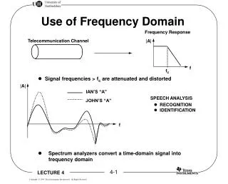
Filtering Signals • The response of a CT, LTI system with frequency response to a sinusoidal signal • Filtering: if or then or is
Four Basic Types of Filters lowpass highpass passband stopband stopband cutoff frequency bandpass bandstop (many more details about filter design in ECE 464/564 and ECE 567)
Phase Function • Filters are usually designed based on specifications on the magnitude response • The phase response has to be taken into account too in order to prevent signal distortion as the signal goes through the system • If the filter has linear phase in its passband(s), then there is no distortion
Linear-Phase Filters • A filter is said to have linear phase if • If is in passband of a linear phase filter, its response to is
Ideal Linear-Phase Lowpass • The frequency response of an ideal lowpass filter is defined by
Ideal Linear-Phase Lowpass – Cont’d • can be written as whose inverse Fourier transform is
Ideal Linear-Phase Lowpass – Cont’d Notice: the filter is noncausal since is not zero for
. . Ideal Sampling • Consider the ideal sampler: • It is convenient to express the sampled signal as where