Download
1 / 24
240 likes | 254 Views
Learn about QZSS L1-SAIF signal offering submeter accuracy differential corrections, integrity functions, and multi-constellation support. Explore how it enhances GPS/GLONASS position availability.

E N D
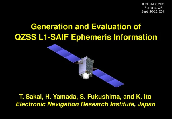
ION ITM 2013 San Diego, CA Jan. 28-30, 2013 QZSS L1-SAIF Supporting GPS/GLONASS Multi-Constellation Augmentation T. Sakai, H. Yamada, K. Hoshinoo, and K. Ito Electronic Navigation Research Institute, Japan
Introduction • QZSS (Quasi-Zenith Satellite System) program: • Regional navigation service broadcast from high-elevation angle by a combination of three satellites on the inclined geosynchronous (quasi-zenith) orbit; • Broadcast GPS-like supplemental signals on three frequencies and two augmentation signals, L1-SAIF and LEX; • The first QZS satellite was successfully launched on Sept. 11, 2010. • L1-SAIF (Submeter-class Augmentation with Integrity Function) signal offers: • Submeter accuracy wide-area differential correction service; • Integrity function for safety of mobile users; and • Ranging function for improving position availability; all on L1 single frequency. • ENRI has been developing L1-SAIF signal and experimental facility: • Possible to extend to augment GLONASS satellites; • Upgraded to support multi-constellation environment including GPS, GLONASS, and QZSS satellites; • Conducted experiment with broadcast of multi-constellation augmentation.
GPS/GEO QZS QZSS Concept • Broadcast signal from high elevation angle; • Applicable to navigation services for mountain area and urban canyon; • Augmentation signal from the zenith could help users to acquire other GPS satellites at any time. • Footprint of QZSS orbit; • Centered at 135E; • Eccentricity 0.075, Inclination 43deg.
Ranging Function QZS satellites GPS Constellation Error Correction Ranging Signal Integrity Function L1-SAIF Signal • Three functions by a single signal: ranging, error correction (Target accuracy: 1m), and integrity; • User receivers can receive both GPS and L1-SAIF signals with a single antenna and RF front-end; • Message-oriented information transmission: flexible contents. User GPS Receivers SAIF: Submeter-class Augmentation with Integrity Function
L1-SAIF Signal • QZSS broadcasts wide-area augmentation signal: • Called L1-SAIF (Submeter-class Augmentation with Integrity Function); • Designed and developed by ENRI. • L1-SAIF signal offers: • Wide-area differential correction service for improving position accuracy; Target accuracy: 1 meter for horizontal; • Integrity function for safety of mobile users; and • Ranging function for improving position availability. • Augmentation to GPS L1C/A based on SBAS techniques: • Broadcast on L1 freq. with RHCP; Common antenna and RF front-end; • Modulated by BPSK with C/A code (PRN 183); • 250 bps data rate with 1/2 FEC; Message structure is identical with SBAS; • Differences: Large Doppler and additional messages. • Specification of L1-SAIF: See IS-QZSS document (Available at JAXA HP).
System Horizontal Error Vertical Error Standalone GPS Standalone GPS RMS 1.45 m 2.92 m Augmented by L1-SAIF Max 6.02 m 8.45 m L1-SAIF RMS 0.29 m 0.39 m Max 1.56 m 2.57 m L1-SAIF Corrections • Example of user position error at Site 940058 (Takayama: near center of monitor station network); • Realtime operation with MSAS-like 6 monitor stations; • Period: 19-23 Jan. 2008 (5 days); • L1-SAIF provides corrections only; • No L1-SAIF ranging. Augmentation to GPS Only Note: Results shown here were obtained with survey-grade antenna and receiver in open sky condition.
GLONASS Support: Motivation QZSS L1-SAIF Augmentation Additional Constellation = GLONASS GPS constellation • Increase of augmented satellites improves availability of position solution; • Chance of robust position information at mountainous areas and urban canyons. • The current SBAS specification already has definition of GLONASS; Easy to support by L1-SAIF.
Time and Coordinate Systems • GLONASS Time: • GLONASS is operating based on its own time system: GLONASS Time; • The difference between GPS Time and GLONASS Time must be taken into account for combined use of GPS and GLONASS; • The difference is not fixed and slowly changing: about 400ns in July 2012; • SBAS broadcasts the difference by Message Type 12; • GLONASS-M satellites are transmitting the difference as parameter tGPS in almanac (non-immediate) data: tGPS = tGPS− tGLONASS. • PZ-90 Coordinate System: • GLONASS ephemeris is derived based on Russian coordinate system PZ-90; • The relationship between WGS-84 • and the current version of PZ-90 • (PZ-90.02) is defined in the SBAS • standard as:
PRN Masks • PRN Mask: • SBAS/L1-SAIF transmits PRN mask • information indicating satellites which are • currently augmented; • PRN number has range of 1 to 210; • Up to 51 satellites out of 210 can be • augmented simultaneously by the single • SBAS/L1-SAIF signal; • But, 32 GPS + 24 GLONASS = 56 !!! • Solution: Dynamic PRN Mask • Actually, PRN mask can change; Controlled by IODP (Issue of Data, PRN Mask); • Change PRN mask dynamically to reflect the actual visibility of satellites from the intended service area. PRN definition for SBAS
Previous Ephemeris IODE=a Next Ephemeris IODE=b Time LTC IOD=b LTC IOD=a LTC IOD=a LTC IOD=a LTC IOD=b IOD (Issue of Data) • IOD indicator along with corrections: • LTC (Long-Term Correction) in SBAS Message Type 24/25 contains orbit and clock corrections; • Such corrections depend upon ephemeris data used for position computation; • IOD indicates which ephemeris data should be used in receivers. • IOD for GPS satellites: • For GPS, IOD is just identical with IODE of ephemeris data.
Previous Ephemeris Next Ephemeris Time Ephemeris Validity Interval LTC IOD=V2|L2 Ephemeris Validity Interval LTC IOD=V1|L1 V2 V1 L1 L2 IOD for GLONASS • IOD for GLONASS satellites: • GLONASS ephemeris has no indicator like IODE of GPS ephemeris; • IOD for GLONASS satellites consists of Validity interval (V) and Latency time (L) to identify ephemeris data to be used: • 5 MSB of IOD is validity interval, V; • 3 LSB of IOD is latency time, L. • User receivers use ephemeris data transmitted at a time within the validity interval specified by L and V.
Perturbation terms in ephemeris Satellite Position • GLONASS ephemeris data: • GLONASS transmits ephemeris information as position, velocity, and acceleration in ECEF; • Navigation-grade ephemeris is provided in 208 bits for a single GLONASS SV; • Broadcast information is valid for 15 minutes or more. • Numerical integration is necessary to compute position of GLONASS satellites; • Note: centripental acceleration is removed from transmitted information. • These terms can be computed for the specific position and velocity of SV; • GLONASS ICD A.3.1.2 gives the equations below (with some corrections).
QZS GPS GLONASS L1C/A, L2P L1-SAIF Signal K-band Closed Loop L1SA L2SA L1C/A, L2P Measured Data L1-SAIF Message GEONET L1SMS QZSS MCS GSI ENRI JAXA Upgrade of L1SMS • L1-SAIF Master Station (L1SMS): • Generates the L1-SAIF message stream and transmits it to JAXA MCS. • Upgrade for supporting GLONASS and QZSS: • Input module: Supports BINEX observables and navigation message records; • Implemented GLONASS extension based on SBAS standards; • User-domain receiver software (MCRX) is also upgraded to be GLONASS-capable; • QZSS is also supported as it is taken into account like GPS.
tcutover Cutover Transition time 180s PRN Mask (IODP=i) PRN Mask (IODP=i+1) FC FC LTC FC FC LTC FC FC LTC FC FC Corrections before cutover Corrections after cutover Dynamic PRN Mask • Dynamic PRN mask: • Changes PRN mask dynamically to reflect the actual visibility of satellites; • Set PRN masks ON for satellites whose pseudorange observations are available; Not based on prediction by almanac information not provided by RINEX; • Semi-dynamic PRN mask: Fix masks ON for GPS and QZSS, and change dynamically only for GLONASS to reduce receiver complexity. • Transition of PRN mask: • Periodical update of PRN mask: updates every 30 minutes; • Transition time 180s is given to users to securely catch the new PRN mask.
^ ^ BGLONASS BGPS True Time GLONASS System Time GPS System Time Receiver Time t tGLONASS tGPS tR Receiver clock for GPS satellites DtGLONASS DtGPS Time offset broadcast to users Receiver clock for GPS satellites -daGLONASS GLONASS Time Offset • Realtime computation: • Computes as the difference between receiver clocks for a group of GPS satellites (and QZSS) and the other group of GLONASS satellites; • Enough accuracy with a filter of long time constant; • Need no almanac information broadcast by GLONASS satellites; • Transmitted to users via Message Type 12 of SBAS.
Experiment: Monitor Stations • Recently Japanese GEONET began to provide GLONASS and QZSS observables in addition to GPS; • Currently more than 150 stations are GLONASS/QZSS-capable; • Data format: BINEX • For our experiment: • 6 sites for reference stations; Reference Station (a) to (f) • 11 sites for evaluation. User Station (1) to (11) • Period: 2013/1/6 01:00 • to 2013/1/9 23:00 (94 hours).
QZSS GLONASS GPS PRN Mask Transition • Reflecting our implementation, PRN mask is updated periodically at every 30 minutes; • Semi-dynamic PRN mask: GPS and QZSS satellites are always ON in the masks; • PRN masks for GLONASS satellites are set ON if the satellite are visible and augmented; • Stair-like shape: because the slot number of GLONASS satellites are assigned increasingly along with the orbit. • IODP (issue of Data, PRN Mask) indicates change of PRN mask.
Elevation Angle GPS GLONASS QZSS PRN Mask Transition 5 deg @ User (7) • Rising satellites appear at 5-12 deg above the horizon; Latency due to periodical update of PRN mask; • However, GPS satellites also have similar latency; Not a major problem because low elevation satellites contribute a little to improve position accuracy.
# of Satellites vs. Mask Angle 16 SVs 9.8 SVs 7.3 SVs @ User (7) • Introducing GLONASS satellites increases the number of satellites in roughly 75%; • QZSS increases a satellite almost all day by only a satellite on the orbit, QZS-1 "Michibiki" • Multi-constellation with QZSS offers 16 satellites at 5 deg and 7.3 satellites even at 40 deg.
User Position Error: Mask 5deg • GPS+GLO+QZS: 0.310m RMS of horizontal error at user location (7); • Looks some limited improvement by using multi-constellation.
User Position Error: Mask 30deg • GPS+GLO+QZS: 0.335m RMS of horizontal error at user location (7); • Multi-constellation offers a good availability even for 30 deg mask.
North South Error vs. User Location: 5 deg 0.421m 0.283m • Expect horizontal accuracy of 0.3 to 0.5m with L1-SAIF augmentation, regardless GLONASS is used or not; • There is a little dependency upon the latitude of user location possibly due to an effect of ionosphere activities.
North South Error vs. User Location: 30 deg 0.425m • The horizontal accuracy is still within a range between 0.3 and 0.5m for the multi-constellation configuration; • The accuracy degrades to 1 or 2.5m for GPS-only single-constellation configuration.
Conclusion • ENRI has been developing L1-SAIF signal: • Signal design: GPS/SBAS-like L1 C/A code (PRN 183); • Planned as an augmentation to mobile users. • GPS/GLONASS/QZSS multi-constellation support: • L1-SAIF Master Station was upgraded to support GLONASS and QZSS in addition to GPS based on the existing SBAS specifications; • Conducted an experiment with broadcast of L1-SAIF signal containing augmentation information of GPS, GLONASS, and QZSS; • Using multi-constellation it can be expected to maintain a good position accuracy even in higher mask angle conditions representing limited visibility conditions. • Further Investigations will include: • Dynamic PRN mask driven by almanac information; • Use of GLONASS observables in generation of ionospheric corrections; • Considerations of different types of receiver for reference/user stations; and • Extension to Galileo.