Download
1 / 54
560 likes | 833 Views
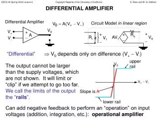
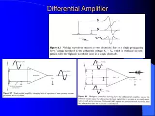
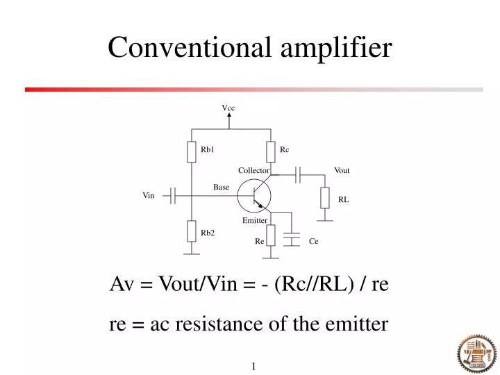
Conventional amplifier. Vcc. Rb1. Rc. Collector. Vout. Base. Vin. RL. Emitter. Rb2. Re. Ce. Av = Vout/Vin = - (Rc//RL) / re re = ac resistance of the emitter. High-frequency transformer-coupled amplifier. Vcc. L. Vout. C1. RL. Rb1. Collector. Base. Vin. Emitter. Rb2. Ce.

E N D
Conventional amplifier Vcc Rb1 Rc Collector Vout Base Vin RL Emitter Rb2 Re Ce Av = Vout/Vin = - (Rc//RL) / re re = ac resistance of the emitter
High-frequency transformer-coupled amplifier Vcc L Vout C1 RL Rb1 Collector Base Vin Emitter Rb2 Ce Re f = 1 / (2 pi sqrt(L C1) Q = f / B Example 2.1
Practical common emitter amplifier with better impedance matching Vcc Rd L Vout C1 RL Rb1 Cd Collector Base Vin Emitter Rb2 Ce Re Better impedance matching Higher Q
Common base RF amplifier Vcc L L Vout Vin RL Cb Re
Wideband amplifier- Class A Vcc Vout L RL Rb1 Collector Base Vin Emitter Rb2 Ce Re Linear amplifier Generally used as single-ended audio amplifiers
Wideband amplifier- Class B Vcc Rb1 Vout RL Vin Compared to Class A: Greater efficiency Larger distortion
Amplifier- Class C Vcc Vout L RL Collector Base Vin Emitter High efficiency Larger distortion
Operating condition Class C amplifiers would improve the efficiency by operating in nonlinear regime, however the input has to be a sinusoidal wave Some means are needed to remove the distortion and restore the signal to its original sine shape
Operation principle The active device conducts for less than 180 degrees of the input cycle The output resembles a series of pulses more than it does the original signal The pulses can be converted back to sine waves by an output tuned circuit
Circuit configuration Vcc Vout L Output RL Input Collector Base Vin Emitter Nonlinear amplifier Sine input -> nonlinear current output -> sine output Fig. 2.12
Pros and Cons of the Class C amplifiers • Pros: • High efficiency, no current in absence of signal • Cons: • The output tuned circuit must be adjusted fairly close to the operating frequency • The amplification is nonlinear
Neutralization Vcc Rd L Vout Cd RL Rb1 Collector Base Vin Emitter Rb2 Ce Re Cn Neutralization capacitor
Oscillator A • Barkhausen criteria: • A x B = 1 • Phase shift must total 0 or integer multiple of 360 degrees B
Using non-inverting amplifier N2 N1 Hartley oscillator B = N1 / (N1 + N2) f = 1/2pi sqrt(LC)
Using inverting amplifier (Hartley oscillator) N2 N2 N1 N1 B = -N1 / N2 B = (N1 + N2) / N1 Example 2.2
Colpitts oscillator (non-inverting amplifier) C2 C1 B = Xc1 / Xct = C2 / (C1 + C2)
Colpitts oscillator (inverting amplifier) C2 C1 B = -Xc1/Xc2 = - C2/C1 Example 2.3
Varactor tuned oscillator C=C0/sqrt(1+2V) Example 2.5
Oscillation frequency of LC circuit See MIT open course ware
Another application of high Q filter Clock recovery by strong filtering effect Before After PTL Oct
Crystal Crystal oscillators achieve greater stability by using a small slab of quartz as a mechanical resonator, in place of an LC tuned circuit Cs Cp Two resonance frequency related to Cs and Cp, respectively
Temperature dependence fT = f0 + k f0(T-T0) Example 2.6 A portable radio transmitter has to operate at temperatures from –5 to 35 degrees. If the frequency is derived from a crystal oscillator with a temperature coefficient of +1ppm/degree C and it transmits at exactly 146 MHz at 20 degree, find the transmitting frequencies at the two extremes of the operating range
Mixers A mixer is a nonlinear circuit that combines two signals in such a way as to produce the sum and difference of the two input frequencies at the output Any nonlinear device can operate as a mixer Vout = A Vi + B Vi2 + C Vi3 + … Second order effects f1- f2 f1+f2 f1 f2
Square law mixers Vout = A Vi + B Vi2 If inputs are two frequencies, the outputs will be: Original frequencies, double frequencies, sum frequencies, and differential frequencies Example 2.7
Diode mixers The V-I curve for a typical silicon diode is nonlinear Diode mixers can operate between reverse and forward biased states Or they can operate with a small forward bias Vin Vout
Transistor mixers Vcc Vout L RL Rb1 Collector Base f2 f1 Emitter Rb2 Re
VLO Vin VLO Vin VLO Vin VLO Vin Other transistor mixers Collector Collector Base Base More commonly used Pull in phenomena Good for high frequencies
Balanced mixers A multiplier circuit, where the output amplitude is proportional to the product of two input signals, can be used as a balanced mixer V1 = sinω1t V2 = sinω2t Vo = V1 x V2 = 0.5 x [cos(ω1t - ω2t) – cos(ω1t + ω2t)]
Applications of balanced mixers Data (…01101001…) AM Modulation Output Signal Carrier Signal input Output Signal AM de-modulation Filter Local oscillator
Detection schemes Homodyne and heterodyne detection One example of heterodyne detection Self-mixing homodyne detection Signal input Output Signal Filter
Phase detector using mixer Signal input The DC output depends on the phase of the two paths
Phase discriminator using diodes Crystal Vin VR Based on diode mixer Details see p482 on the Chinese book
Phase locked loop Phase detector LPF Amp VCO Output Input Capture range Lock range Example 2.8
Simple frequency synthesizer Phase detector LPF Amp VCO Output Input / N divider FM and AM channel spacing Example 2.9
A practical example – 29M to 10G synchronization circuit 29MHz / 6 circuit 29MHz amplification, digitization and frequency division circuit (All capacitors are 0.1uF).
Experimental results Spectrum of 4.827MHz square signal wave. Span: 500Hz, RB: 30Hz. Spectrum of 4.827MHz square signal wave. Span: 500Hz, RB: 30Hz.
Pre-scaling Phase detector LPF Amp VCO Output Input Fixed /Q Fixed /M Programmable /N Example 2.10
Frequency translation The movement of a block of frequencies is called a frequency translation Two configurations: Synthesizer with frequency shifting Synthesizer with mixer in the loop Example 2.11
Transmission lines Coaxial cables (solid dielectric, air dielectric) Parallel line cables (television twin-lead, open-wire line, shielded twin-lead) Twisted pair cable
Two models of short transmission line section Balanced line Unbalanced line
Step and pulse response of lines Characteristic impedance: the ratio of voltage to current through the transmission line with a step signal Concept of matched line Characteristic impedance Z0 = sqrt[(R + jwL) / (G + jwC)] Many lines approach Z0 = sqrt(L/C) Example 14.1, 14.2
Reflection (step input) Open end scenario Short end scenario Pulse input…
Some definitions • Γ = Vr/Vi: reflection efficient • Γ = (ZL – Z0) / (ZL + Z0) • Meaning of the above equation: • To have zero reflection, ZL has to be equal to Z0 • By measuring Γ, ZL can be derived to probe the internal characteristic of the load • Example 14.13
An example to know the internal parameters of a tunable laser Transmission line Source S11 Parameters Reflector biased at 10 mA Is (A) 1.79E10-5 q 4.47 Rp (ohm) 0.1 Rs (ohm) 0.1 Rsub (ohm) 1.0 Cp (pF) 4.58 Cs (pF) 355 Lp (nH) 21.4 S11 = (ZL – Z0) / (ZL + Z0)
Voltage driver is better than current driver Y. Su et al, IEEE PTL Sept. 2004 Current response Optical response
Wave propagation In a matched line, a sine wave moves down the line and disappear into the load. Such a signal is called a traveling wave Example 14.5 RF Phase shifter