Download
1 / 15
150 likes | 373 Views
Fast Orbit Feedback and Beam Stability at the Swiss Light Source. V. Schlott , M. Böge, B. Keil, P. Pollet, T.Schilcher. Introducing the Swiss Light Source Stability Requirements The SLS “digital” BPM System FOFB Architecture FOFB Results Medium Term Beam Stability at SLS

E N D
Fast Orbit Feedback and Beam Stability at the Swiss Light Source V. Schlott, M. Böge, B. Keil, P. Pollet, T.Schilcher • Introducing the Swiss Light Source • Stability Requirements • The SLS “digital” BPM System • FOFB Architecture • FOFB Results • Medium Term Beam Stability at SLS • Conclusions and Outlook
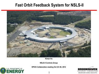
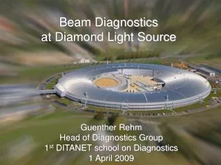
The Swiss Light Source – Accelerator Complex Pre-Injector LINAC Parameters LINAC Storage Ring Storage Ring Parameters Booster Parameters Booster
The Swiss Light Source – Beamlines • 7 beamlines in operation (May 2004) • 2 beamlines under commissioning • 2 beamlines under construction • 3 beamlines planned
Noise Sources:medium term – diurnal temperature, filling pattern and machine refills • 100 mm up to 1 mm • short term – ID gap changes and polarization switching • – ground vibration, cooling water, crane motion, • – traffic, rf-drifts, injector operation • 10 mm up to 100 mm Stability Requirements for SLS – A 3rd Generation Light Source • Angular Stability: photon energy resolution of 10-4 to 10-5 in planar crystal monochromators • require: DQbeam < 1 mrad • Position Stability: S/N-ratios of 10-3 to 10-4 on samples require: Dxbeam and Dybeam < s/10 • corresponding to Dybeam~ 1 mm in SLS low b ID-straights at 1% coupling • User Requirements: autonomous andindependent ID gap changes transparent to other users • Bandwidth Requirements: are given by the integration times of experiments • >> 100 s …. inelastic x-ray scattering • 0.1 – 100 s …. protein crystallography (PX) • …. m-tomography (CMT) • < 0.1 s …. time resolved XAS and x-ray diffraction • …. dichroism spectroscopy
Instrumentation for Monitoring and Control of Beam Stability: Short Term Motion • Performance of “Digital” BPM System: resolution at 4 kS/s: 0.8 mm current dep.: < 5 mm (@ fixed gain) stability: < 2.5 mm (@ < ± 1°C) The DBPM system is operated under “top-up” conditions (I = 330 mA) at fixed gain levels providing highest reproducibility and stability while excluding current dependencies! • Corrector Power Supplies: The resolution of the SLS corrector power supplies was specified to 15 ppm to obtain residual (vertical) rms orbit deviations of < 0.25 mm (200 seeds have been simulated with TRACY) Achieved resolution: ~ 1 ppm Achieved short term stability (< 60 s): < 10 ppm Achieved long term stability (> 1000 h): < 30 ppm
Global Stability with SOFB Slow Orbit Feedback SOFB • data points from all 72 BPMs are averaged over 0.32 s • they correspond to rms deviation from “golden orbit” • centralized data processing • uses all 72 BPMs and all 72 correctors per plane • RF frequency correction for path length changes • corrector setting through controls network • alternate correction of vert. and horiz. planes • correction rate < 3 s (~ 0.4 Hz) • in operation during Aug. 2001 – Nov. 2003 orbit distortions due to ID-gap and RF frequency changes cannot be corrected by SOFB
DBPM system consists of RF front end, • Quad digital receiver and DSP • CS interface via VME-bus • FOFB is integral part of DBPM system • fiber optic links (40 MB/s) via DSP2 • system is expandable for additional • RF and/or Photon BPMs Fast Orbit Feedback FOFB Architecture • the use of all 72 BPMs and 72 correctors in • both transverse planes allows de-centralized • data processing with 6 BPMs and 6 corrector • magnets per station (sector) • off energy orbits are corrected by SOFB using • central RF frequency as additional control parameter • circular fiber optic network for data distribution • initializing and control via central BD server • sampling and correction rate at 4 kS/s • correction bandwidth up to 100 Hz DBPM System - the Core Piece of the FOFB
FOFB - Transfer Function (closed loop performance) Theoretical Bode plots as function of sampling rate 20 Hz - f = 1 kS/s 45 Hz - f = 2 kS/s 100 Hz - f = 4 kS/s • -10dB damping reached at: • assuming PID controller • bandwidth of vacuum chamber and corrector • magnets including eddy currents taken into account Measured Bode plot (both transverse planes) OverallTime Delays: • quad digital receiver settings ~ 600 ms • position calculation (DSP1) ~ 60 ms • global data exchange ~ 8 ms • feedback algorithm and • SVD matrix calculation (DSP) ~ 70 ms • data transfer via PS controller ~ 150 ms • asynchronous mode of QDR < 250 ms
vacuum pumps ? girder eigenmodes booster FOFB – Power Spectral Densities • measured at tune BPM outside of feedback loop (bx = 11 m, by = 18 m) • no ID-gap changes FOFB – Accumulated Power Densities (1 – 150 Hz) • Examples (1 – 150 Hz): • tune BPM (by = 18 m): sy = 1.2 mm • ID 6S (by = 0.9 m): sy = 0.28 mm
FOFB – “In Loop” Performance • data points from all 72 BPMs are averaged over • 0.32 s representing a relevant bandwidth for • most SLS users • data points correspond to RMS deviation from • “golden orbit” • orbit distortions due to ID gap changes are • corrected, which makes ID gap changes • transparent to all users • vertical RMS during “top-up” run ~ 0.06 mm • horizontal RMS during “top-up” run ~ 0.71 mm • “blurring” of global horizontal RMS distribution • due to drifts of dispersion orbit, which is corrected • by a high level SOFB on RF frequency • this does not affect users, since ID straight • sections are dispersion free vertical RMS beam offset [mm] horizontal RMS beam offset [mm]
FOFB – External Reference with Photon BPMs • still strong gap dependence of photon BPMs • which needs calibration !!! • but photon BPMs can be used as external • reference, whenever ID-gaps are unchanged X-BPM position [mm] • photon BPM signals show systematic drifts • of photon beam in the order of ± 1.5 mm at • ~ 10 m distance from source points X-BPM position [mm]
Systematic Effects of FOFB Slow FB on Photon BPM Readings Photon BPM signal (at 06S) at ~ 10 m from source point data points are integrated over period of 1 s Photon BPM signal (at 06S) at ~ 10 m from source point data points are integrated over period of 1 s • systematic oscillations have been suppressed by • implementing a slow, high level feedback on • photon BPM readings. • resulting photon beam stability at the location • of first optical elements of the material sciences • and protein crystallography beamlines < 1 mm ! • systematic oscillations of ± 1.5 mm at the location • of the photon BPMs (~ 10 m from source point) • are not caused by temperature drifts of DBPM • electronics but could be correlated with injection • clock cycle! • bunch pattern dependence of electronics • bunch pattern control (feedback) is under commissioning
50°C 20°C Quadrupole BPM chamber BPM support girder alignment rail Instrumentation for Monitoring and Control of Beam Stability: Medium Term Motion Deformation of SLS Storage Ring Vacuum Chamber due to Thermal Loads FEA-simulations indicate movements of up to 2 mm/°K in the transverse plane at the positions of the BPM blocks in case of thermal transients in the machine. • Position Monitoring System (POMS) of BPM Stations: Dial gauges equipped with linear encoders (0.5 mm res.) as sensing devices attached to quadrupole magnets “top-up” operation avoids thermal transients in storage ring
Medium Term Beam Stability at SLS due to “Top-Up” Operation • “Top-up” operation stabilizes beam current • in storage ring within a pre-defined dead • band (here: 200 ± 0.5 mA) • Only thermal transients caused by • “beam dumps” and/or decaying beam induce • mechanical movements of BPM blocks • Mechanical movements of all BPM blocks • in reference to adjacent quadupole magnets • are monitored with POMS system with a • resolution of 0.5 mm • During “top-up” operation no active • stabilization of mechanical movements is • needed. • Apart from mechanical stability due thermal equilibrium, “top-up” operation allows to operate • BPM electronics at constant gain levels under most stable conditions!
Conclusions and Perspectives • The FOFB stabilizes the electron beam orbit in the SLS storage ring up to • 100 Hz bandwidth to a mm-level in reference to a pre-defined “golden orbit” • Integrated short term electron beam stability (~ 0.1 – 100 Hz) at the SLS low gap • ID-straights in the vertical direction are below 0.3 mm • ID gap changes are in user’s control and fully transparent to other users • Additional slow feedback on photon BPMs stabilize photon beams on a sub-mm • level at the location of the first optical elements of the beamlines • Medium term stability is constantly monitored by POMS system • “Top-Up” operation leads to thermal equilibrium in SLS storage ring and • leads to mm medium term (minutes to days) stability • FOFB will be expanded by integration of additional RF and photon BPMs