Download
1 / 9
120 likes | 473 Views
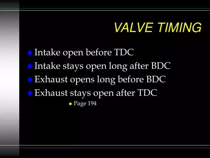
VALVE TIMING. Intake open before TDC Intake stays open long after BDC Exhaust opens long before BDC Exhaust stays open after TDC Page 194. VALVE OVERLAP. End of Exhaust , Begining of Intake strokes Longer overlap produces more power at high RPM Longer overlap produces poor vacuum at idle

E N D
VALVE TIMING • Intake open before TDC • Intake stays open long after BDC • Exhaust opens long before BDC • Exhaust stays open after TDC • Page 194
VALVE OVERLAP • End of Exhaust , Begining of Intake strokes • Longer overlap produces more power at high RPM • Longer overlap produces poor vacuum at idle • Long overlap, (late exhaust closing) causes “Lope” • Long overlap cause valve to piston clearance problems • Page 196
CHECKING CAM TIMING • Degreeing in the cam • Dial Indicator • Degree Wheel • Use Intake centerline Method
ROCKER ARM RATIO • Standard Ratio is 1.5:1 • 1.6:1 and 1.75:1 are also common ratios • .300” lift at cam would be .450” at valve with 1.5 ratio rocker
MEASURING VALVE LIFT • Must use a “solid” lifter and Dial Indicator • Or special tool • Net Valve Lift - measured at cam • Gross Valve Lift - measured at valve
PERFORMANCE CAMSHAFTS • Camshafts are a compromise • Preformance - Economy • Low RPM Torque - High RPM Horsepower
PERFORMANCE CAMSHAFTS • Coil Bind • Valve Springs • Retainer to Valve Guide Clearance • Rocker arm slot length
LIFT • High Lift Cams increases all valve train wear • Minumum .125” clearance between • valve stem seal and retainer. • Limited by valve to piston clearance
DURATION • Longer duration increases RPM for Max Horsepower • Shorter duration produces more low and mid range Power • SAE at .006” • Performance manufactures (SAE) at .050” • High compression can offset for long duration