Download
1 / 61
620 likes | 899 Views
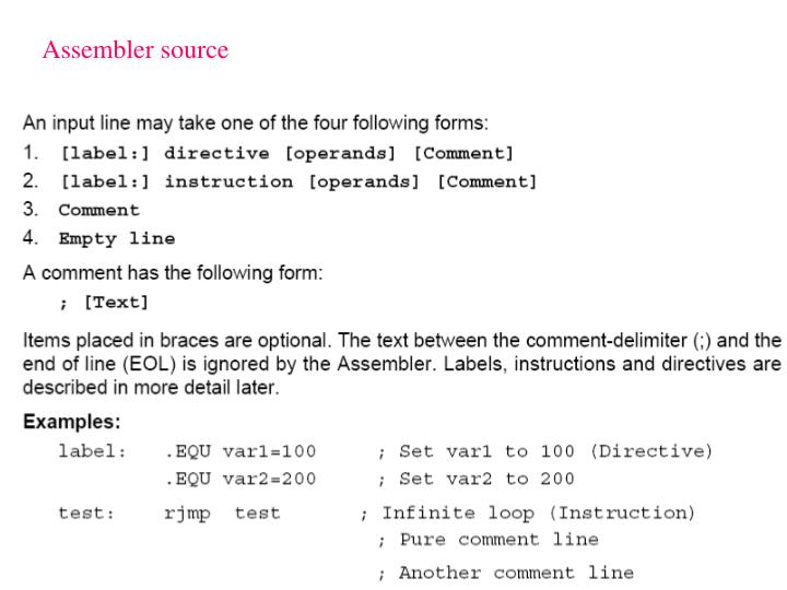
Assembler source. Editor and message windows. ASSEMBLER DIRECTIVES Change or adjust the way the assembler works with the code. Assembler directives can be divided into the following groups DEFINE SEGMENTS .cseg .dseg .eseg .csegsize .org PROGRAM MEMORY .db .dw .cseg .org EEPROM

E N D
ASSEMBLER DIRECTIVES • Change or adjust the way the assembler works with the code
Assembler directives can be divided into the following groups DEFINE SEGMENTS .cseg .dseg .eseg .csegsize .org PROGRAM MEMORY .db .dw .cseg .org EEPROM .db .dw .eseg .org SRAM .byte .dseg .org REGISTER & CONSTANTS .def .equ .set CODING .macro .endmacro .listmac .include ASSEMBLER OUTPUT .device .exit .list .nolist
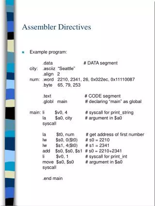
1a) DEFINE SEGMENTS .cseg .dseg .eseg .csegsize .org ; Start program segment Word Counter for programs, Byte Counter for SRAM and EEPROM, The values of the Location Counters are defined by .org
1b) PROGRAM MEMORY .db .dw .cseg .org 1c) EEPROM .db .dw .eseg .org Define (initialize) values using .DB and .DW
1d) SRAM .byte .dseg .org Define code name for SRAM locations using .BYTE
1e) REGISTER & CONSTANTS .def .equ .set Rename Registers Name constants Rename constants (can be used many times with different value)
1f) CODING .macro .endmacro .listmac .include Arguments 0 and 1 are r2 and r1 respectively .def pseudo instruction (assembler directive) for sreg in INCLUDE file
1g) ASSEMBLER OUTPUT .device .exit .list .nolist
2) EXPRESSIONS Operands Functions Operators 2.1) Operands
2.2) Functions 2.3) Operators
Unary operators Binary operators
4.3) Description of the views The following views are available: Output tabs Build window – Message window – Find in files function – Breakpoints Workspace tabs Project view I/O view Register – Processor core register – Stack – I/O register Info view Interrupt vector – AVR package – I/O register Watch view Memory view SRAM – Flash Memory – Register – I/O register – EEPROM Register window Dissasembler window T
4.3.1) Output tabs Build window – Message window – Find in files function – Breakpoints The Build view. Output from the compiler / assembler is routed to thiswindow. The result of the compilation / assembly can be read here.When compiling or building projects output messages and warnings are printedin this view. Double click on an error or you to the source code location. The key F4 can also be used, and will go to thenext error. Breakpoints. Lists all active breakpoints in all modules. Breakpoints can beenabled, disabled and removed in the view. More details in section 4 of thedebugging document.
4.3.2)Workspace tabs Project view I/O view Register – Processor core register – Stack – I/O register Info view Interrupt vector – AVR package – I/O register 4.3.2.1) Project view
4.3.2.2) I/O View Register – Processor core register – Stack – I/O register
The view has 4 fields of information for the I/O registers, name, value, bits and address.
4.3.2.3) Info view Interrupt vector – AVR package – I/O register This view is static and show all interrupts, pin configuration and available IO adresses for the selected device.
4.3.3) Watch view With the watch window you can view and edit all defined symbols when debugging. EditDouble click on an empty line to type a variable name. Quick watch Highlight the variable you want to watch in the editor and select quickwatch. You can look at the variable and its contents and alternatively add it to the watch view.
4.3.4) Memory View Editing Change the value by clicking on the location and type a new value. This can also be done with the ASCII values in the right border (if shown).
4.3.6) The Disassembler window The disassembler window shows your program code disassembled. Program execution and AVR instructions can be followed in this view. +000000B9: 2700 CLR R16 Exclusive OR +000000BA: BF05 OUT 0x35,R16 Out to I/O location +000000BB: E800 LDI R16,0x80 Load immediate +000000BC: BF04 OUT 0x34,R16 Out to I/O location
4.4) ΑΝΑΠΤΥΞΗ ΚΩΔΙΚΑ AVR Assembler To get started is simple, when AVR Studio loads, select the AVR Assembler from theproject dialog box, select a project name directory where the project shall reside, and click finish. A project file is created, an *.asm file is available in the editor window and you are set for writing your first instructions. Check out the online AVR assembler has it's own book where all instructions and directives are explained. In addition, there is context sensitive help in the editor window, just write aninstruction, place the cursor on top of the instruction and press F1, and you will gethelp on the syntax on the selected instruction.
4.5 Simulator The simulator supports all existing new AVR devices, look at the tools and devicesupport for an overview. It simulates not only the CPU, but nearly all the on-chip I/Omodules and memory, as well as the I/O ports. Special care has been taken to ensureproper simulation of the device, and there are only small differences betweensimulated and actual behaviour. The simulator does not connect to outside hardwareand has to be stimulated from pre-calculated stimuli files. But as the device issimulated entirely inside the PC memory, the user has extended visibility of all theon-chip functions.
If you develop for a specific device in mind you should include the *.def.inc file forthe part. Each part has it's own *.inc file that defines all internal registers, bits and alot of other stuff that makes it simpler for you to write code for the part. In additionthe *.inc file sets the device directive for the assembler, letting the assembler knowwhich part you are developing for. The part files are found in the \ProgramFiles\Atmel\AVRTools\AVRAssembler\ΐppnotes folder on your computer. Ainclude file for ATmega8 will typically be named "m8def.inc". You do not have togive a path with the *.inc file as long as it is found in the default directory. Press F7 in order to compile. The result of the compilation will show in thepreviously described Build view in the output window frame.
4. 6) Programming the Target AVR Device STK500 is controlled from AVR Studio, version 3.2 and higher. To program a hex file into the target AVR device, select "STK500" from the "tools“menu in AVR Studio. Select the AVR target device from the pull-down menu on the “Program” tab andlocate the intel-hex file to download. Press the "erase" button, followed by the "program" button. The Status LED will nowturn yellow while the part is programmed, and when programming succeeds the LEDwill turn green. If programming fails, the LED will turn red after programming, see the "Trouble-shooting guide" (Help in STK500 user's guide).
1) 8 διακόπτες 2) 8 LED 3) Δύο σειρές από ακροδέκτες (headers). 4) Μία περιοχή με υποδοχές διαφόρων τύπων AVR (target sockets) και τις υποδοχές για εξωτερικές συνδέσεις των ακροδεκτών των AVR. Κάθε φορά τοποθετείται ένας μόνο AVR . 5) Μία περιοχή με διακλαδωτήρες (jumpers) και μία ενδεικτική λυχνία τροφοδοσίας των υποδοχών.
6) Μία σειρά από ακροδέκτες (headers) και υποδοχή για κρύσταλλο. 7) Το τμήμα προγραμματισμού των μνημών των AVR, τους διακόπτες reset και προγραμματισμού και την ενδεικτική λυχνία κατάστασης προγραμματισμού. Υπάρχουν επίσης ένας άλλος AVR ο 8535 (Master AVR) και το κύκλωμα για τις τάσεις RS232, το ΜΑΧ202. 8) Τον διακόπτη τροφοδοσίας, την λυχνία τροφοδοσίας και τις υποδοχές τροφοδοσίας και RS232C (για PC και επιπρόσθετη για άλλη χρήση).