Download

1 / 36
370 likes | 665 Views
Treatment Planning Above and below the diaphragm Why is it so complex? Patty Sponseller, CMD. Hodgkin’s Lymphoma. It’s just AP/PA right?. Mantle. Para-aortics. Although AP/PA a lot going on here!. Radiation Fields. Mantle covers chin and just below diaphragm

E N D
Treatment Planning Above and below the diaphragm Why is it so complex? Patty Sponseller, CMD Hodgkin’s Lymphoma
It’s just AP/PA right? Mantle Para-aortics
Radiation Fields Mantle covers chin and just below diaphragm Laterally “flash” skin to include both axilla Involved field radiation Inverted Y covers paraaortic, pelvic and inguinal lymph nodes
Mantle RT Radiation to a large area of the neck, Chest and axilla Cover all the main lymph node areas above the diaphragm Shielding to part of the lungs, heart and shoulders Mantle is derived from the name of a garment much like a cloak in medieval times
PATIENT THICKNESS CHANGES PATIENT CONTOUR IRREGULARITIES DIFFERENT HETEROGENITIES MISSING TISSUE BEAM CHARACTERISTICS GEOMETRIC MATCH Variation with the DD throughout the fields
Why is this? • Basic dose distribution data is obtained under standard conditions • Homogenous density in a water phantom • Perpendicular beam incidence • Flat surface
The beam may be obliquely incident with respect to the surface Surface may be curved or irregular in shape Under these conditions, standard DD are not applicable without corrections During Treatment
Beam data includes profile scans across the beam, depth doses and output factors (ratio of the dose measured for a specific F S standard to a 10 cm2) measured for every machine energy and many square field sizes. This measured data is used to determine the many, many free parameters in the Pinnacle model for EACH linear accelerator. In Pinnacle we are then modeling the energy that comes from the head of the Tx unit including all the scatter within the head that affects the energy spectrum.
Modeling – Convolution Algorithm An integral that calculates at every point within the dose grid. That dose calculation includes the attenuation of the beam as it travels through tissue times the energy fluence of energy spectrum times the energy kernel.
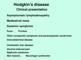
Imaging Conventional X rays Ultrasound CT scan PET (FDG) Ability to screen for distant Dz Uptake in nodal areas that look normal on CT False positives Not good at detecting marrow involvelment
Simulation for Adjacent Fields Maintain patient position when all fields are treated Proper immobilization for entire torso Clam shell used if pelvis RT for males Consider oophoropexy for females Supine position with arms akimbo Immobilization indexed to treatment couch
Matching new fields with previously TX • Tattoo documentation cannot be overemphasized • Compare prior DRR’s and portal images • Examine the chart carefully for possible changes during prior RT • Reproduce prior RT with new scan to ensure which segment of spinal cord was irradiated
Goal is a Homogenous Dose DistributionAdjacent fields have the same divergence
Adjacent Fields Adjacent fields do not match divergence Dose discrepancies over spinal cord
Inverted Y May need to split up inverted Y into 2 fields for adult or tall adolescent Otherwise-
You have this problem The larger inverted Y does not match the divergence of the mantle field Hot and cold spots
Blocking Spleen/Paraortic Fields or Inverted Y usually can accommodate MLC Mantle Fields typically are a combination of MLC and Cerrobend blocking Lung Block shapes are usually too complex for MLC May consider a larynx block on AP field
Portal Imaging See the combination here
Field Blocks Blocks are shaped or tapered to match the divergence of the beam This minimizes block transmission pneumbra (partial transmission of the beam at the edges of the block) Do we do this for all our photon blocking at UWMC?
Custom Blocking • Lipowitz Metal • Cerrobend (brand name) • Approx 83% of Pb density • Low melting point • Materials making up Cerrobend are • Bismuth • Lead • Tim • Cadmium
How thick are the blocks? Half Value layer The thickness of the material required to attenuate the intensity of the beam to half its original value How many HVL’s in MV photon blocking?
Original Value 100% 50% 25% 12.5% 6.25% 3.12% 1.56% 5 HVL’s
How thick are the blocks? 5 HVL’s of Cerrobend needed What is the HVL thickness of Cerrobend? 1 HVL of Cerrobend is 1.5 cm thick In the megavoltage range of photons the most common used thickness is 7.5 cm Which is equivalent to about 6 cm of pure lead
Mantle Fields Dose Distribution is calculated with cerrobend blocking Pinnacle will not allow Step N Shoot with custom blocking Here we use a “Poor Man” Technique Treat more than one field, close jaws and adjust weighting
Other Techniques Use wedge on AP field if FS allows Compensators Decimal
Para/Spleen or Inverted Y Usually MLC’s can be used for blocking on all fields May require Step N shoot for hot spots
Point under a block 17 cm 4.5 cm 6.25 cm 17 cm
Fields 17 X 17 cm = 17 cm 2 4.5 x 17 cm= 7 cm 2 6.25 x 17 cm= 9 cm 2 Calculate the dose under a block at 10 cm depth