Download
1 / 28
360 likes | 1.18k Views
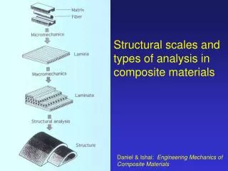
Aerospace Structures and Materials: Composite Failure. Dr. Tom Dragone Orbital Sciences Corporation. Fracture Toughness Crack Size. Fatigue Crack Initiation Crack Growth. Metal Yield Rupture. Composite FPF LPF. Stability Buckling Crippling. JOINT LOADS

E N D
Aerospace Structures and Materials:Composite Failure Dr. Tom Dragone Orbital Sciences Corporation
Fracture Toughness Crack Size Fatigue Crack Initiation Crack Growth Metal Yield Rupture Composite FPF LPF Stability Buckling Crippling JOINT LOADS Weld , Braze Bond, Bolt Structure Design / Analysis Process GLOBAL LOADS Aerodynamics Inertial Applied GEOMETRY Planform Skin Construction Spar/Rib Layout MATERIALS Metal Composite SIZING Thickness Ply Orientation SHEAR-MOMENT DIAGRAM Section Loads Structure Idealization Stiffness Lamination Theory BOX BEAM ANALYSIS Component Loads (Cap Forces, Shear Flow) FAILURE ANALYSIS MS>0? Done Yes No
Motivation • Composite failure is very different from metal failure Discussion Questions: • How does a composite “yield”? Does Von Mises or Tresca hold? • How does a composite “fail” or “rupture”? What are some of the mechanisms involved? • Are composites better or worse than metals under fatigue loading? • How would a composite fracture? Does LEFM apply? • What additional failure modes are possible with composites?
VON MISES: TRESCA: COMPOSITE: Failure Envelopes • Metal Failure: Homogeneous and Isotropic • Composite Failure: Inhomogeneous and Anisotropic
UNIDIRECTIONAL LAMINATE BIDIRECTIONAL LAMINATE FPF, LPF LPF METAL FPF Ultimate Yield Stress-Strain Behavior
Ply Failure • First Ply Failure (FPF) • Similar to yield • First indication of non-reversible deformation • Change in slope of loading curve (non-linear) • Laminate has residual load-bearing potential • Last Ply Failure (LPF) • Similar to Ultimate • No more load bearing potential • Rupture
Ply Failure Criteria First Ply Failure Criteria • Maximum Stress • Maximum Strain • Hill (Maximum Distortion Energy) • Tsai-Wu (Quadratic) • Matrix Tension • Matrix Compression Last Ply Failure Criteria • Fiber Tension • Fiber Compression No Description of Failure Mechanism Indicates Failure Mechanism
Failure Analysis Implementation • “Weakest Link” Analogy • Failure criteria apply at the ply level • When one layer fails, the entire laminate fails • Which Failure Criteria to Use? • Depends on the particular fiber/matrix combination • Must test to determine most appropriate criteria • Failure Envelopes for Composites are Rarely Used • Complex ply interactions make visualization difficult • Sometimes can be helpful for a particular laminate
Failure Criteria Maximum Stress X= Longitudinal Strength Maximum Strain Y= Transverse Strength S= Shear Strength Hill (Max Energy) Fij= Empirical Factor ~ -0.5 Tsai-Wu Xt= Tensile Strength Xc= Compressive Strength
Failure Criteria Matrix Tension Matrix Compression Fiber Tension Fiber Compression
Progressive Damage Models • FPF Usually Implies Transverse Failure of Matrix • Fiber can still continue to bear load • Does not cause rupture • Causes change in failed ply stiffness • Set Ply Transverse Modulus and Shear Modulus = 0 • Load is Shifted to Other Layers • Other Plies MAY Fail Leading to FPF = LPF or • Stable Equilibrium Reached Such That Laminate Can Take More Applied Load • Process Continues Until Fiber Failure Occurs in Weakest Ply • Progressive Damage Models Typically Used in Failure Investigations, Not in Design Because They are Cumbersome
COMPFAIL Process • Apply Loads • Return Strains and Curvatures • Return Equivalent Moduli (For Symmetric Laminates ONLY) • Return Ply Strains and Ply Stresses • e1, e2, e6, s1, s2, s6 for Global (Laminate) Coordinate System • ex, ey, es, sx, sy, ss for Local (Material) Coordinate System Two Values: Top and Bottom of Ply
COMPFAIL Failure Analysis Process • Calculate Failure Criteria for Each Ply
COMPFAIL Failure Analysis Process • Calculate Failure Criteria for Each Ply • Calculate R Value for Each Ply • R = Factor x Applied Load That Gives Failure Index = 1 • R ~ 1/(Failure Index)^2
COMPFAIL Failure Analysis Process • Calculate Failure Criteria for Each Ply • Calculate R Value for Each Ply • Search for Minimum R Value Through Thickness
COMPFAIL Failure Analysis Process • Calculate Failure Criteria for Each Ply • Calculate R Value for Each Ply • Search for Minimum R Value Through Thickness • Summarize Values
COMPFAIL Failure Analysis Process • Calculate Failure Criteria for Each Ply • Calculate R Value for Each Ply • Search for Minimum R Value Through Thickness • Summarize Values Color Code: Green = FI > 1.5 Yellow = 1.25 < FI < 1.5 Red = FI<1.25
0 45 -45 90 90 -45 45 0 Delamination Crack Initiation
Delamination Delamination Growth Interface Between Plies
Impact Damage Impact Visible Damage Ultrasonic Image Internal Damage
Impact Damage Core Damage Internal Rib Damage
FATIGUE Strain Low Cycle Fatigue ec High Cycle Fatigue eth Cycles Other Failure Modes • eth ~ 6000me for many resins • Design Below This to Eliminate Microcracking and Fatigue Damage Fiber Breakage Interface Debonding Matrix Cracking Interface Shear Fatigue Limit for Matrix
0 45 -45 90 90 -45 45 0 Delamination