Download
1 / 38
380 likes | 508 Views
Overview of SoC Design process (2). Chip integration & Software development. References. 1) G. Martin, H. Chang, et al, Surviving the SOC Revolution: A Guide to Platform Based Design, Kluwer Academic Publishers, Sept. 1999.

E N D
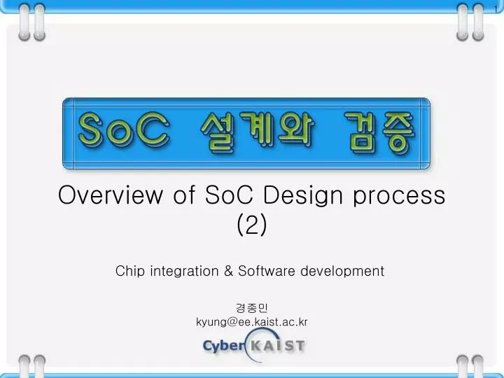
Overview of SoC Design process (2) Chip integration & Software development
References • 1) G. Martin, H. Chang, et al, Surviving the SOC Revolution: A Guide to Platform Based Design, Kluwer Academic Publishers, Sept. 1999. • 2) K. Keutzer, S. Malik, A. R. Newton, J. M. Rabaey, and A. Sangiovanni-Vincentelli, System Level Design: Orthogonalization of Concerns and Platform-Based Design, invited paper, IEEE Transactions on Computer-Aided Design, Vol. 19, No. 12, December 2000.
Four major areas of SoC design(PBD) • Block(IP) authoring • VC delivery • Chip integration • Software development • (Design environment)
Executable specification (Chip Integration) • Chip or product requirements captured and specified in terms of explicit functionality and performance criteria, to be translated into design constraints for the ensuing process • Can be given as simulatable, high-level models with abstract data types and key performance metrics, which can be used for evaluating the appropriateness of the specification itself and testing against the downstream implementation. • Typically given in C, C++, SDL.
System Analysis (Chip Integration) • Develops and verifies the algorithm elements in the design specification • Such developed algorithms are THE base for the fundamental partitioning between HW and SW such that first-order constraints of the specification (application standards, target technology selection) are met.
VC Selection/Integration (Chip Integration) • Evaluation of both the blocks available and platform elements for selection • Make modifications (or, refinements) for the available blocks • For new blocks, define the interface requirements and functional behavior.
Partition/Constraint budget (Chip Integration) • HW elements are partitioned and detailed performance, power, area and interface constraints defined for each. • Implementation technology is assessed against each partition and the integration design. • Architectural elements such as power, clock, bus, test, I/O are all put in place. • Initial risk guardband is developed identifying areas where the implementation will need particular attention
RTL Mapping (Chip Integration) • The design is mapped into a hierarchical RTL structure, which instantiates VC blocks and selected platform elements (bus, clock, power), and kicks off block design and modification activities.
Interface Generation (Chip Integration) • The interface is manually modified or automatically through parameter change.
Integration Planning (Chip Integration) • Detailed physical planning of the block locations • High-level routing of bus and assembly wiring • Consideration of clock trees, test logic, power controls, analog block locations with noise analysis, and block constraints from overall chip plan.
Constraint Definition (Chip Integration) • Refine the overall constraints based on the floorplan to drive the final layout/route of the integration architecture. • Critical chip-level performance paths and power consumption are analyzed to adjust the constraints based on the interconnect delay and power level extracted from the floor plan.
Clock/Power/Test (Chip Integration) • Generate the clock trees • Lay down power buses and domains considering noise from all different sources (digital-to-analog isolation, ground bounce, simultaneous switching) • Insert test logic
Hierarchical routing with signal integrity (Chip Integration) • Hybrid of high-level assembly and area routing • Considering constraints and signal integrity • Delays and power factors are reported to analysis tools. • Assumptions and assertions made in the VC selection stage are difficult to maintain with VDSM technologies.
Performance simulation (Chip Integration) • Useful for estimating the feasibility of the design goals, or for evaluating different implementation architecture alternatives leading to algorithm selection, architectural choices (HW/SW partitioning tradeoff, VC selection). • Based on high-level models with limited details • ex.) critical path, key functional mode for CPU • Very fast; can be part of system analysis
Behavioral simulation (Chip Integration) • Behavioral models can be either BFM (Bus functional model) for checking interface property only, or FFM (full functional model) for checking internal as well as interface functions. • FFM can be timing-correct (cycle-accurate; signal behavior correct in pin and clock cycle/phase) or not. • Slower than performance simulation, but fast enough.
HW/SW Coverification (Chip Integration) • Check whether SW correctly works with HW. • HW is mostly BFM, while SW runs on model of the target CPU (ex; Instruction Set Simulator) • SW can be testbench for the HW
HW/SW Codesign and Coverification (Chip Integration) • HW/SW Codesign consisting of 5 phases; • Functional exploration • Architectural mapping • HW/SW partitioning ; divides the system into HW and SW components with specifications for each passed to detailed implementation phase of the design • HW and SW implementation • System integration • HW/SW Coverification occurs during the implementation and integration phase. • Brings the traditional divergent HW and SW implementation activities back together to validate the consistency of the ensuing HW and SW implementation and satisfaction of the system specification
HW/SW Cosimulation(Chip Integration) • There are a variety of HW/SW cosimulation techniques available with different profiles; • Raw performance ; turn-around time • Timing accuracy • Model (for the processor) availability • Debuggability (visibility of internal states)
HW/SW Cosimulation(Chip Integration) • A> Techniques requiring Models* (* ‘Model’ represents software model for the processor.) • 1) Nano-second accurate model; • ns-accurate timing for all pins plus complete functionality • Slow due to large number of events with each pin changing signals any time • 2) Cycle accurate model (zero-delay); • Delegates all events at the rising(falling) clock edge • 3) Instruction level model ; • Only the values in the register and memory are correct. • Ignores the internal pipeline, hazards, interlocks related with micro-architecture; superscalar ordering effects and pipeline stalls cannot be modelled.
HW/SW Cosimulation(Chip Integration) • B> Techniques requiring no Models • 1) Synchronized handshake; • Applicable when HW and SW communicates asynchronously, i.e, when time between transactions has no effect on functionality • No need for the processor model (that is, if the SW works by itself, it should work with HW as well); SW model can run as a native code on any fastest available workstation • Overall speed is limited by the hardware simulator performance.
HW/SW Cosimulation(Chip Integration) • B> Techniques requiring no Models • 2) Virtual hardware; • On top of SW running on the host workstation, hardware is also modeled as pure software (no relation to the real HW) running on WS, e.g., disk I/O is mapped through the native OS. • Therefore, HW is not debugged, just SW.
HW/SW Cosimulation(Chip Integration) • B> Techniques requiring no Models • 3) Bus-functional model ; • Processor model reflects only its interaction with the bus, without its internal (full-functional) behavior. • Elaborate test benches can emulate the trace as generated by real software. • Therefore, only the HW part can be simulated, not the SW part running on the processor. • Performance evaluation, like MIPS, is not possible.
HW/SW Cosimulation(Chip Integration) • B> Techniques requiring hardware Models (for the processor); • Hardware modeller ; • Most accurate model from functionality point of view • Use actual hardware, i.e., ARM processor chip or PowerPC chip, instead of the generated software model of the processor • Useful when the processor is very complex, or when software model is not available • Processor internal state invisible • Network round trip delay is caused for every HW/SW interaction.
HW/SW Cosimulation(Chip Integration) • B> Techniques requiring hardware models (for the processor); • Hardware emulation, or in-circuit emulation (ICE*) (* ICE was used, until about ten years ago, to denote MDS, Microprocessor Development System used for developing system hardwares as well as appl. software.) • Processor, as well as HW part, are mapped on either an array of FPGA’s (Axis or old Quickturn product), or an array of specially-coined processors (Mentor Celaro or Quickturn) • Add-on boards can be installed for memory or other OTS products. • Separate emulation-purpose library is needed for both HW and SW. • Roughly one-tenth speed of real chip
Rapid Prototyping (Chip Integration) • Useful for verifying design elements (HW or SW) in the context of the integration platform architecture and/or with existing VC’s. • Bonded-out core availability helps. • Used for early SW development before the silicon implementation • Ex.; Aptix’ System Explorer ; reconfigurable prototyping engine based on FPIC (Field-Programmable Interconnect Chip) for inter-module interconnect, as well as FPGA- and other standard product modules such as DSP, microprocessors for implementing each module (as a daughter board)
Simulation Acceleration/Hardware(in-circuit) Emulation (Chip Integration) • Quickturn(Cadence)’s Palladium/CobaltPLUS based on ASIC’s, Mercury based on custom FPGA (Cadence), Mentor’s Celaro, iKOS • HE ; Emulation Hardware is tested against real/live signals from target environment, although at 1/10-th speed. • SA ; Same Hardware is excited by the artificially generated test bench, which can sit on the workstation interacting in cycle-based mode (lock-step mode), or transaction-based mode, or synthesizable testbench mode where testbench is synthesized into the Hardware.
Formal Property/Protocol (interface) Checker (Chip Integration) • Formal property checker is an efficient means for some limited applications, i.e., to verify the bus interface logic against the specified bus protocol.
RTL/cycle simulation (Chip Integration) • Goal is to verify both function and timing. • Based on RTL model • Allows cycle-based acceleration if applicable, while gate/event-level simulation when necessary (that means model should have cycle-accurate, or better timing) • Test benches can be mixed among those from the higher-level and more detailed ones in this level. • Relatively slow; therefore used mainly for debugging critical points
Hierarchical, Static Timing & Power Analysis (Chip Integration) • Static timing analysis needs guidance (from the dynamic simulation) on which logic paths to take. • Static power calculation for the whole chip is to be done in a hierarchical basis and also depends on the circuit switching pattern, which is obtained from dynamic simulation, or from estimations based on clock rates.
Coverage Analysis (Chip Integration) • Determines the efficiency and robustness of the test bench • Checks whether all possible branches in RTL have been exercised; calculates the number of logic states tested.
Formal Equivalence Checking (Chip Integration) • Validate gate-level representation against the RTL representation using mathematical techniques.
Physical Verification (Chip Integration) • Extract transistor-level netlist from the final layout to verify whether it matches the gate-level netlist, while meeting all electrical and physical rules. • Repeated blocks are to be abstracted for hierarchical checking for speed-up.
Test Integration (Chip Integration) • Test solutions for each block on the chip are various. A chip-level test architecture knitting together all these heterogeneous solutions is necessary to obtain a cost-effective manufacturing tests. • Chip-level test architecture includes; • Chip test coverage estimation mechanism • Estimated time on the tester • Pins dedicated for test mode • TAP(test access protocol) logic and conventions • How to create and verify test vectors in the real physical environment • Test screening procedures • Access scheme for internal memory and analog blocks • BIST scheme • Performance-level test • Manufacturing diagnostic test for yield enhancement
Secure IP Merge (Chip Integration) • Software or methods for decoding the protecting devices into an actual layout is needed for successful chip integration.
Supplementary Stuffs (Chip Integration) • Integration platform; an architectural environment to facilitate design reuse for SoC design and manufacture, being targeted to specific applications in consumer market • Integration Guide; design methodology, styles, techniques, tools, requirements and constraints • IP Portfolio; Collection of VC’s pre-staged and pe-characterized for a particular integration architecture, for a particular application range. • SW development links; Pre-verified pairs of device and its device driver. • PCB Tools Link; Communicates the effects of IC package, bonding leads/contacts, and PCB to IC design tools.