Download
1 / 50
500 likes | 522 Views
Explore the convective cooling of gases to superheat steam and maximize the efficiency of steam generators. Learn about superheaters, economizers, and air pre-heaters.

E N D
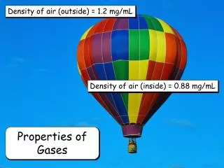
Convective Cooling of Gases for Superheating of Steam By P M V Subbarao Professor Mechanical Engineering Department I I T Delhi Generation of Most Bountiful State of Working Fluid (Useful Enthalpy)…
Furnace Energy Balance Enthalpy to be lost by hot gases: Water walls Economizer Furnace
Capacity of Flue Gas Total Thermal Power available with flue gas: Rate of steam production:
Steam Generator : Convective Heating Surfaces HT thru Licking of tubes by Flue gas……..
Capacity of Super heaters • Super heater heats the high-pressure steam from its saturation temperature to a higher specified temperature. • Super heaters are often divided into more than one stage. • The enthalpy rise of steam in a given section should not exceed • 250 – 420 kJ/kg for High pressure. > 17 MPa • < 280 kJ/kg for medium pressure. 7 Mpa – 17 MPa • < 170 kJ/kg for low pressure. < 7 MPa
Paths of Steam and Gas Drum Water walls Economizer
Flow Arrangement of Super Heaters Furnace Wall
Thermal Balance Equation for PSH • Energy given out by flue gas: • Energy absorption for a Platen SH
Thot gas,in Thot gas,out Tcold steam,out Tcold steam,in Mechanism of Heat Transfer :Generalized Newton’s Law of Cooling • Rate of heat transfer from hot gas to cold steam is proportional to: • Surface area of heat transfer • Mean Temperature difference between Hot Gas and Cold Steam.
Thot gas,out Thermal Profiles of Fluids in A HX Thot gas,in Tcold steam,out Tcold steam,in Thot gas,in Thot gas,out Tcold steam,out Tcold steam,in
Log Mean Temperature Difference • Rate of Heat Transfer • U Overall Heat Transfer Coefficient, kW/m2.K
Platen Superheater • Platen Superheater : Flat panels of tubes located in the upper part of the furnace, where the gas temperature is high. • The tubes of the platen SH receive very high radiation as well as a heavy dust burden. • Mechanism of HT : High Radiation & Low convection • Thermal Structure: • No. of platens • No. of tubes in a platen • Dia of a tube • Length of a tube
S1 S2 Convective Superheater (Pendant) • Convective super heaters are vertical type (Pendant ) or horizontal types. • The Pendant SH is always arranged in the horizontal crossover duct. • Pendant SH tubes are widely spaced due to high temperature and ash is soft. • Transverse pitch : S1/d > 4.5 • Longitudinal pitch : S2/d > 3.5. • The outside tube diameter : 32 – 51mm • Tube thickness : 3 – 7mm
S1 S2 Convective Superheater (Horizontal) • The horizontal SH are located in the back pass. • The tubes are arranged in the in-line configuration. • The outer diameter of the tube is 32 – 51 mm. • The tube thickness of the tube is 3 – 7 mm. • The transverse pitch : S1/d = 2 – 3. • The longitudinal pitch :S2/d = 1.6 – 2.5. • The tubes are arranged in multiple parallel sets. • The desired velocity depends on the type of SH and operating steam pressures. • The outside tube diameter : 32 – 51mm • Tube thickness : 3 – 7mm
Thermal Balance in Super Heater • The energy absorbed by steam • The convective heat lost by flue gas • Overall Coefficient of Heat Transfer, U
Reheater • The pressure drop inside reheater tubes has an important adverse effect on the efficiency of turbine. • Pressure drop through the reheater should be kept as low as possible. • The tube diameter : 42 – 60mm. • The design is similar to convective superheaters. • Overall Heat Transfer Coefficient : 90 – 110 W/m2 K.
Economizer • The economizer preheats the feed water by utilizing the residual heat of the flue gas. • It reduces the exhaust gas temperature and saves the fuel. • Modern power plants use steel-tube-type economizers. • Design Configuration: divided into several sections : 0.6 – 0.8 m gap
Thermal Structure of Economizer • Out side diameter : 25 – 38 mm. • Tube thinckness: 3 – 5 mm • Transverse spacing : 2.5 – 3.0 • Longitudinal spacing : 1.5 – 2.0 • The water flow velocity : 600 – 800 kg/m2 s • The waterside resistance should not exceed 5 – 8 %. Of drum pressure. • Flue gas velocity : 7 – 13 m/s.
Thermal Balance in Economizer. • The energy absorbed by steam • The convective heat lost by flue gas • Overall Coefficient of Heat Transfer, U
Air Pre-Heater • An air pre-heater heats the combustion air where it is economically feasible. • The pre-heating helps the following: • Igniting the fuel. • Improving combustion. • Drying the pulverized coal in pulverizer. • Reducing the stack gas temperature and increasing the boiler efficiency.
Stockholm 1920The Ljungström Air Preheater The first installation in a commercial boiler saved as much as 25% of the fuel consumption.
Historical Significance of Landmark • In a modern Steam generator the Ljungström Air Preheater provides up to 20% of the total heat transfer in the boiler process. • The Ljungström Air Preheater only represents 2% of the investment. • The Ljungström Air Preheater is a remarkable invention in many ways. • It saves the fuel so much that the cost of the preheater is generally recovered after only a few months. • It has been estimated that the total world-wide fuel savings resulting from all Ljungström Air Preheaters which have been in service is equivalent to 4,500,000,000 tons of oil. • An estimate shows that the Ljungström Air Preheaters in operation annually saves about $30 Billion US.
The Idea: One Shot Two Birds Data for the hand fired boiler before and after the installation of Ljungström Air Preheater is as follows:
Combustion Losses C & R losses Hot Exhaust Gas losses APH Economizer CSH Pendent SH Reheater Platen SH Furnace absorption
COMBINED CYCLE POWER PLANT GAS INLET P=10bar CC T=1500C T=8500C P=10bar TURBINE G COMP T=1000C T=500C STACK P=2bar P=1bar T=5500C HP IP LP AIR INLET HRSG T=5000C P=170bar TURBINE T=500C G PUMP P=1bar P=.1 bar T=500C T=600C CONDENSER
Types of HRSG • Basic types of standard design of heat recovery steam generators are differentiated by the direction of the flue gases flow. • Vertical HRSG • Small footprint • Simple concept of service • Hanging design of heating surfaces • Horizontal HRSG • Small construction height • High cycling ability • Operational flexibility • Hanging design of heating surfaces
Horizontal HRSG Vertical HRSG
Heat Exchanging Curve ~5500C ~1000C ~400C
Types of Evaporator Sections • D-Frame evaporator layout • O-Frame evaporator layout • A-Frame evaporator layout • I-Frame evaporator layout • Horizontal tube evaporator layout
D-Frame evaporator layout • This configuration is very popular for HRSG units recovering heat from small gas turbines and diesel engines. • It is a very compact design and can be shipped totally assembled. • Main Drawback: The bent tube arrangement quickly causes the module to exceed shipping limitations for units having a large gas flow
O-Frame evaporator layout • This configuration has probably been used for more years than any of the others. • It has the advantage of the upper header being configured as the steam separation drum. • Alternately, The upper header can be connected to the steam drum by risers. • This allows more than one O-Frame evaporator to be connected to the same steam drum. • Results in shipable modules being able to handle very large gas flows.
A-Frame evaporator layout • This configuration is simply a variation of the O-Frame Evaporator. • It was popular for services with a large amount of ash, since the center area between the lower drums could be configured as a hopper to collect and remove solid particles.
I-Frame evaporator layout • In the past twenty years, this configuration has become the most popular. • This type module can be built in multiple axial modules or in multiple lateral modules, allowing it to be designed to accept any gas flow. • There are numerous variations of this design where tube bundles may contain one, two, or three rows of tubes per header. • It is also, normally, more economical to manufacture, ship and field construct. • The tube bundles may be shipped to field installed in the modules, or as loose bundles which are installed into a field erected shell.
Horizontal tube evaporator layout The horizontal tube evaporator is used, not only for heat recovery from Gas Turbine exhaust, but for recovery from flue gases in Refinery and Petrochemical furnaces also. • It has similar size limitations due to shipping restrictions similar to the O-frame modules. • It is generally a less expensive unit to manufacture than the other configurations.
Schematic Diagram of a Simple HRSG ~1000C ~5500C
Single Pressure Rankine Cycle ~5500C ~1000C ~400C