Download
1 / 11
110 likes | 258 Views
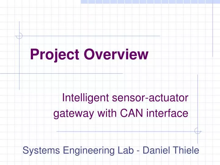
Intelligent sensor-actuator gateway with C AN interface. Project Overview. Systems Engineering Lab - Daniel Thiele. Project Team. Motivation. Existing mobile robot chassis: CAN is used for on-board communication every drive unit is controlled by a central intelligence Future purposes:

E N D
Intelligent sensor-actuator gateway with CAN interface Project Overview Systems Engineering Lab - Daniel Thiele
Motivation • Existing mobile robot chassis: • CAN is used for on-board communication • every drive unit is controlled by a central intelligence • Future purposes: • Possibility for semi-intelligent behaviour • Every drive should possess a seperate µController • Communication relay to a off-unit monitoring tool • Communication between other drive units • Controllability of behaviour of the drive unit
Block Diagram - System Robot Chassis DriveUnit 1 DriveUnit 2 CentralIntelligence CAN Bus DriveUnit 3 DriveUnit 4
Block Diagram - Existing Drive Unit Drive Unit n Drive Unit n-1 Motor Controller CentralIntelligence Velocity Encoder CAN Bus Angular Encoder Brake Switch Drive Unit n+1
Resulting Problems • High Bus Load • 4 x 4 CAN bus modules over 1 CAN bus line extensive bandwith usage • No Data Logging • Data logging must been contributed by central intelligence Increased CPU load
General Tasks • Data logging • Saving of measured values in a ring buffer • React to requests by central intelligence • Communication with central intelligence • Implementation of a basic protocol over CAN • Control of EPOS positioning controller • Implementation of functions for EPOS control
Block Diagram - New Drive Unit Drive Unit n Drive Unit n-1 Motor Controller MicrocontrollerBoard CentralIntelligence Velocity Encoder CAN Bus Angular Encoder Brake Switch Drive Unit n+1
Block Diagram – Microcontroller Microcontroller Board Internal Memory C P UFreescaleHCS12 CAN Interface CAN Interface Motor Controller / Encoders Central Intellegince RS232 Interface Debugging / Monitoring
Initialize Operation System Initialize Digital I/O Initialize CAN / RS232 interfaces Initialize System functions Main loop Check for drive unit CAN messages and store to circular buffer Check for and process central intelligence CAN commands Select necessary commands for drive unit Load desired drive unit CAN messages from circular buffer Send CAN messages to drive unit and central intelligence Check for and process RS232 debug commands Send appropriate RS232 messages to debugging unit Activity Chart - Software
Thank you for your attention! For further information ...