Download
1 / 55
550 likes | 558 Views
Learn about orthographic projection and how to create the necessary views to accurately describe an object. Explore the glass box method and understand the arrangement of views for third angle projection.

E N D
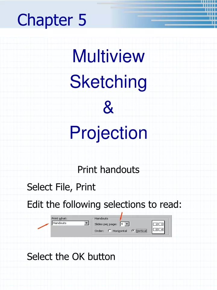
Chapter 5 Multiview Sketching & Projection Print handouts Select File, Print Edit the following selections to read: Select the OK button
Orthographic Projection • A system of drawing views of an object using perpendicular projectors from the object to a plane of projection (I.e. paper)
Six Standard Views • Top, front, right side, left side, back and bottom • Front • Usually shows most detail • If applicable – should show object in operating condition (I.e. car)
View Placement (3rd angle projection) • Front view usually shows the most detail Projection Lines • Why must views be arranged so that they align? • To make it possible for someone to interpret the drawing.
The Glass Box Metaphor • Imagine that the object you are going to draw is positioned inside a glass box, so that the large flat surfaces of the object are parallel to the walls of the box. • 2 horizontal planes • 2 frontal planes • 2 profile planes • From each pointon the object, imagine a ray, or projector perpendicular to the wall of the box forming the view of the object on that wall or projection plane. • 2 horizontal planes (top and bottom views) • 2 frontal planes (front and back views) • 2 profile planes (right and left side views)
Unfolding the Glass box • For Third Angle Projection (the method in the U.S.) • Imagine that the walls of the box are hinged and unfold the views outward around the front view. • This will give you the standard arrangement of views for 3rd Angle Projection which is used in the US, Canada, and some other countries.
Third Angle Projection: Symbol forthird angle projection shown on dwg Third angle projection Standard for USA, Canada and our class! First Angle Projection: First angle projection Primarily used in Europe and Asia! Symbol forfirst angle projection
DEMO • If a point, line or plane is in one view, it must be in all the views.
Precedence of Lines • When visible lines, hidden lines and center lines coincide remember: • Visible lines take precedence over hidden lines • Hidden lines take precedence over center lines, For example: Figure 5.32
Example • Do Hands-On 3 together • Need • HB pencil • Engineering Calculation Paper • Model • Instructions (Sept. Schedule of Assignments in Angel) • Follow instructions • Remember specs for the border & title block are included in the Penn State Erie Graphics Standards and in Handouts folder in Angel • Label • Views – TOP, FRONT, etc.
Hands-On 4 • Instructions on the web
Chapter 5 Multiview Sketching & Projection Part 2
Necessary Views • A sketch or drawing should only contain the views needed to clearly and completely describe the object. Choose the views that show the shape most clearly, have the fewest hidden lines, and show the object in a usual, stable, or operating position. One view drawing of a shim One view drawing of a connecting rod
Reference Line or Fold Line 3 Views - Most Common Three views necessary? Which view could be eliminated? Top 45° Views? Depth Planes? Dimensions? H F Width Depth Projection Lines Height F P Front Right Side
Transferring Dimensions • Mitered System • Dividers or Scale
This will be the left edge of the right side view clear space Mitered System • Determine spacing necessary between the front and right side views. • For example, when dimensioning, more space is needed between the views.
Bottom edge of the top view Intersection Left edge of the right side view clear space Mitered System • Extend a projection line from the bottom edge of the top view and one from the left side of the right side view until they intersect.
From point of intersection 45º Mitered System • Extend a 45° angled line from the point of intersection.
Mitered System cont’d. 2 1 3 4 • Project additional points, surface by surface. 1 1 3
Mitered System cont’d. 2 1 8 7 6 3 5 4 • Project additional points, surface by surface.
Mitered System cont’d. 2 1 8 7 6 3 5 4 • Draw the view locating each vertex of the surface on the projection and miter line.
Dividers or Scale • With folding lines • Without folding lines
Also Review • PENN STATE ERIE DRAFTING STANDARDS
Chapter 5 Multiview Sketching & Projection Part 3
Configuration Rule NORMAL SURFACE Plane is shown true shape and size. In other words, parallel to one of the principal planes. EDGE EDGE TS SURFACE B
EDGE EDGE Configuration Rule INCLINDED SURFACE Surface is perpendicular to one plane and will show as an edge on that plane. And the surface is tipped, or inclined, to adjacent planes. The surfaces in these views are foreshortened.
EDGE TS EDGE NORMAL PLANE Configuration Rule OBLIQUE PLANE Surface is not parallel or perpendicular to any principal plane. ? PLANE EDGE
Configuration Rule ? PLANE • Is this one correct?
Points, Lines & Planes • If all else fails, • Break the object down to simpler shapes • Locate the height, width and depth of each point.
Chapter 5 Multiview Sketching & Projection Part 4
1/8” DASH 1/16” GAP ¾” – 1-1/2” LONG Center Lines Thin dark line Purpose of a center line? To show location of a hole, arc, cylinder, etc.
Center Lines Extend center line ¼” past the hole HOW MANY CENTER LINES MISTAKES? Extend center line ¼” past the hole
Center Lines • ¼” past the end of the hole and/or cylinder End of cylinder End of hole End of hole
1/16” GAP Precedence of Lines ¼” FROM END OF HOLE HIDDEN LINES TAKE PRECEDENCE OVER CENTER LINES OBJECT LINES TAKE PRECEDENCE OVER HIDDEN LINES
If longer than 1-1/2” add a dash in the middle INCORRECT Center Lines 1/16” gap
Projection of an Object Fillets and Rounds: Self locating, so do NOT add center lines, but do draw where sharp corner would be.
Projection of an Object Why? POOR PRACTICE PREFFERED Adds clarity
Projection of an Object POOR PRACTICE PREFFERED PRACTICE
Runout POOR PRACTICE PREFFERED PRACTICE Projection of an Object
Chapter 5 Multiview Sketching & Projection Part 5