Download
1 / 33
350 likes | 838 Views
Power Line Communication. Presented by : Amani Shelbayeh Lara Nasser Sawsan Salah. Contents. system concept Transmitter Receiver Transmitter circuits Receiver circuits Hardware

E N D
Power Line Communication Presented by : Amani Shelbayeh Lara Nasser Sawsan Salah
Contents • system concept • Transmitter • Receiver • Transmitter circuits • Receiver circuits • Hardware • Problems and solutions • Further scope
TRANSMITTER Side
Device 1 P1.0 at pin 12 D1 Device 2 P1.1 at pin 13 D2
MCU Tx PCB AT89C2051
Frequency ranges 60 KHz 75 KHz
RECEIVER Side
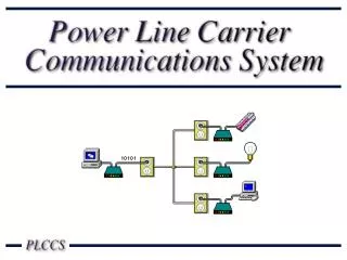
Line interface hardware transmitter receiver
PLL output 60 KHz logic 0 (0v)
Hard ware • PCB • Orcad why PCB: 1.Accuracy 2.Shape
steps Search libraries for suitable footprint 1.Schematic circuit 2. layout, footprint Or create a new footprint
Transmitter Receiver
problems Noise disturbance PLL circuit
solutions 1. BPF simulation
solutions 2. Flexible components
Further Scope • Internet access over power line • Plug and play • update hardware • add routers at transformer section • servers,protocols and standards
The End Thank You