Download
1 / 39
390 likes | 560 Views
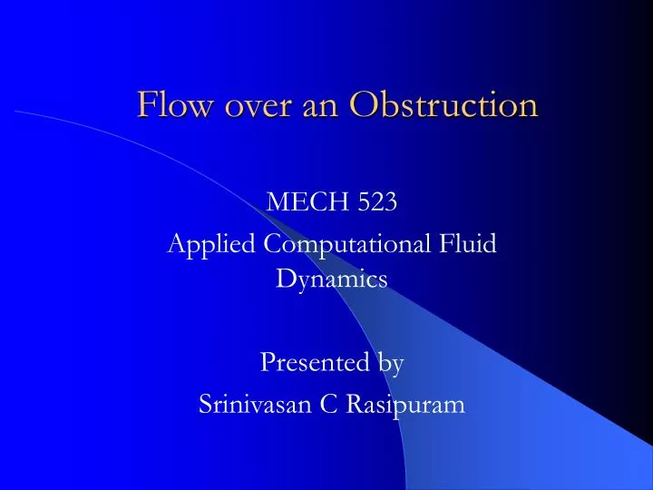
Flow over an Obstruction. MECH 523 Applied Computational Fluid Dynamics Presented by Srinivasan C Rasipuram. Applications. Chip cooling Heat sinks Use of fire extinguishers at obstructions

E N D
Flow over an Obstruction MECH 523 Applied Computational Fluid Dynamics Presented by Srinivasan C Rasipuram
Applications • Chip cooling • Heat sinks • Use of fire extinguishers at obstructions • Though there are no significant applications for flow over obstructions, this model is the bench work for researchers to compare their work and findings.
Tw Case 1 u T 4 cm 2 cm 0.5 cm 10 cm
u T Tw 4 cm 0.5 cm 0.5 cm 0.5 cm 0.5 cm 0.5 cm 10 cm Case 2
Navier-Stokes Equations • Continuity • No mass source has been assumed.
Momentum is the molecular viscosity of the fluid.
Energy Turbulent thermal conductivity keff = k + kt Sh – Volumetric heat source • Brinkman Number where Ue is the velocity of undisturbed free stream • Viscous heating will be important when Br approaches or exceeds unity.
Typically, Br ≥ 1 for compressible flows. • But viscous heating has been neglected in the simulations as Segregated solver assumes negligible viscous dissipation as its default setting. • Viscous dissipation – thermal energy created by viscous shear in the flow.
Standard k-є Turbulence Model k - Turbulent Kinetic energy є - rate of dissipation of turbulent kinetic energy
k and є equations • k and є are obtained from the following transport equations:
where Gk represents the generation of turbulent kinetic energy due to mean velocity gradients Gb is the generation of turbulent kinetic energy due to buoyancy YM represents the contribution of the fluctuating dilatation in compressible turbulence to the overall dissipation rate C1є, C2є, C3є are constants k and є are the turbulent Prandtl numbers for k and є respectively
Eddy or Turbulent viscosity • The model constants C1 = 1.44, C2 = 1.92, C = 0.09, k = 1.0, = 1.3 (Typical experimental values for these constants)
Turbulence Intensity • Turbulence Intensity
Ideal gas model for Density calculations and Sutherland model for Viscosity calculations • Density is calculated based on the Ideal gas equation. • Viscosity calculations • C1 and C2 are constants for a given gas. For air at moderate temperatures (about 300 – 500 K), C1 = 1.458 x 10⁻⁶ kg/(m s K0.5) C2 = 110.4 K
Reynolds Number calculation • For flow over an obstruction, is the density of the fluid V is the average velocity (inlet velocity for internal flows) D is the hydraulic diameter is the Dynamic viscosity of the fluid
Re for V = 0.5 m/sec • For this problem, V = 0.5 m/sec, air = 1.225 kg/m3, air = 1.7894 e–5 kg/m-sec
Inlet Boundary Velocity at inlet 0.5 m/sec. Temperature at inlet 300 K Turbulence intensity 10% Hydraulic diameter 3.5 cm Outlet boundary Gage Pressure at outlet 0 Pa Backflow total temperature – 300 K Turbulence intensity 10% Hydraulic diameter 3.5 cm Solver and Boundary conditionsSolver – Segregated
Wall boundary conditionsHeat sources • No heat flux at top and bottom walls • Stationary top and bottom walls • Volumetric heat source for the (solid) obstruction – 100,000 W/m3
Case 1 – Grids Number of nodes - 4200 Number of nodes - 208372 Number of nodes - 162938
Case 2 - Grids 4220 nodes 79984 nodes 42515 nodes