Download
1 / 21
210 likes | 226 Views
Learn about geometric optics, refraction, lens focal points, and ray tracing rules for clear image formation. Understand how magnification and focal lengths determine image characteristics.

E N D
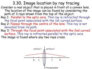
The Geometric Optics of Image FormationGraphical Ray Tracing
Using Refraction to Focus Light. n1=1 n1=1 Glass Lens in Air Parallel Rays n2=1.5 Focal point of lens Optical Axis Focal length of lens, f
Parallel rays come to focus at one pointon the image plane. n1=1 n1=1 Glass Lens in Air n2=1.5 Optical Axis Parallel Rays different direction Image Plane Focal length of lens, f
A Chief Ray is a ray heading towardor away from the center of the lens. n1=1 n1=1 Glass Lens in Air Examples of Chief Rays n2=1.5 Optical Axis Focal length of lens, f
Thin Lens Approximation:Chief Rays pass through the lens without deviation. n1=1 n1=1 Glass Lens in Air Examples of Chief Rays n2=1.5 Optical Axis Focal length of lens, f
We identify two very important rays: (A) Collimated Rays: These are the rays that are parallel to the optical axis. These rays come to focus at the focal point. (B) Chief Rays: These are the rays that go through the center of the lens on the optical axis. These rays are un-deviated.
(A) Ray (A) passes through the focal point. (B) Ray Tracing Rule: Select ONLY two tracing rays, one of type (A), and one of type (B), each from the tip of the object. Ray (B) is not deviated. Light from the object passes through the lens. Follow the Ray Tracing Rule Thin Lens Object Optical Axis f
Light from the object passes through the lens. Follow the Ray Tracing Rule Thin Lens The point of intersection is where the tip of the object comes to a clear focus. Object (A) (B) Optical Axis All other rays from this point must come to focus at the same point. f
h' M = h This is how a projector works. Object is a slide h Light Source f f h'
h h' h' M = h Magnification: The ratio of the size of the image to the size of the object. Magnification < 1 in this example, so the image is smaller than the object. Object Optical Axis f
Traditional Ray Tracing Terms Focal lengths for a thin lens in air: f = f' Object (collimated ray) (chief ray) h h' f' f L L' Object distance and height (L, h) Image distance and height (L, h)
h' M = h Try some different object locations, L. We observe 6 special cases. Object distance = L Image distance = L' h h' f f
Case (I) Object distance L = Image formed at the focal point, and magnification = 0 h h' = 0 f f h' M = = 0 h
looks small & inverted eye h' M = h Case (II) L between and 2f. As object moves to the right, the image size increases. h h' f f Image is real and inverted.
looks small & inverted eye h' M = h h h' f f
looks same size & inverted eye 2f 2f h' M = h Case (III) At L = 2f, h = h', and M = 1. h h' f f
Case (IV): L between 2f and f, (a) the image is still inverted, and (b) h' > h, and M > 1. eye 2f 2f h' M = h h' still increases as the object moves toward the lens. looks larger & inverted h h' f f
For L between 2f and f, (a) the image is still inverted, and (b) h' > h, and M > 1. eye 2f 2f h' M = h h' still increases as the object moves toward the lens. looks much larger & inverted h f f h'
eye 2f 2f h' M = h Case(V): L = f. The rays are parallel. They cross at infinity, so h' = = M. This is the point of maximum confusion! looks very confusing h f f
Case (VI): L between f and the lens. The rays diverge and look AS IF they come from an image that (a) is erect and (b) enlarged, h'>h, m > 1. eye This is called a "virtual image". We look through the lens, and it is a magnifying glass! h' M = > 1 h h f f The rays diverge!!
eye This is how a magnifying glass works! This is called a "virtual image". We look through the lens, and it is a magnifying glass! h' M = > 1 h h f f The rays diverge!!