Download
1 / 48
480 likes | 668 Views
CHAPTER. Refrigeration Components. 14. Instructor Name: (Your Name ). Learning Objectives. Describe the purpose of the compressor, condenser, metering valve, and evaporator. Explain the construction of the compressor, condenser, metering valve, and evaporator.

E N D
CHAPTER Refrigeration Components 14 Instructor Name:(Your Name)
Learning Objectives • Describe the purpose of the compressor, condenser, metering valve, and evaporator. • Explain the construction of the compressor, condenser, metering valve, and evaporator. • Illustrate the operation of service valves and Schrader valves. • Describe the purpose and construction of a vibrasorber.
Learning Objectives (continued) • Demonstrate the operation of a thermostatic expansion valve. • Explain the superheat setting of the TXV. • Describe the mounting location of a sensing bulb. • Determine the superheat setting of the TXV. • Explain the purpose of the distributor. • Describe the purpose of the receiver tank.
Learning Objectives (continued) • Compare the drier materials and explain the purpose of the filter dryer. • Describe the purpose and operation of the heat exchanger • Describe the purpose and operation of the accumulator. • Explain the purpose of pressure regulating devices. • Describe the purpose and operation of the different types of refrigerant safety valves.
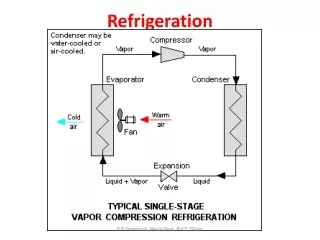
The Four Basic Component • The Compressor • The Condenser • The Metering Device • The Evaporator • Refrigerant, the fifth basic component
The Compressor • Pumps refrigerant through the system • Pressurizes the vapor refrigerant • Raises the temperature of the refrigerant • Draws a very low suction pressure • High discharge and low suction pressures help control the boiling of the refrigerant
Compressor Operation • Refrigerant passes through suction throttling valve (if equipped) into compressor crankcase. • Piston moves down cylinder, refrigerant is drawn in through suction reed valve. • Piston moves upward, refrigerant compresses to 50:1 ratio. • Compressed vapor exits through the discharge valve plate to discharge manifold.
Service Valves • Located on compressor suction and discharge ports • Allows service manifold connection • Can isolate the compressor for service or repairs • Back seated- isolates service port • Mid seat- opens service ports • Front seat- isolates compressor from system
CAUTION Care must be taken to NEVER front seat the discharge service valve while the compressor is operating. Even thought the high pressure cut-out switch might be positioned below the valve, it would not operate fast enough to prevent major damage to the compressor and prevent possible personal injury.
Vibrasorbers • Flexible suction and discharge lines • Positioned at the compressor • Prevent engine and compressor vibrations from reaching the copper piping of the refrigerant system • There are two types of vibrasorbers • Typical discharge vibrasorbers are made up of bellows shaped stainless steel center and a covering of braided stainless steel wire • Typical suction vibrasorber made up of reinforced fabric covered hoses, often using replaceable mechanical fittings
Condenser • Located outside of controlled space • Releases heat from controlled space to outside air • Consists of copper tubing running through aluminum cooling fins • Refrigerant changes state from a high pressure hot vapor to high pressure cooler liquid
Receiver Tank • Acts as storage tank for refrigerant • Usually contains one or two sight glasses • Usually have inlet and outlet service valve • Refrigerant can be isolated between receiver and compressor for downstream service
Filter Dryer • Filters and dries refrigerant • Located in liquid line between receiver outlet and TXV • May be between compressor and condenser • May be between evaporator and compressor • Three different materials commonly used • Silica Gel • Activated Alumina • Molecular Sieve
Heat Exchanger • Located in liquid line between receiver and TXV or outlet of evaporator • Twoimportant functions: • Subcools liquid refrigerant before TXV • Evaporates any liquid refrigerant before it reaches the compressor
Thermal Expansion Valve • Division between high and low side of system • Modulates the flow of refrigerant to the evaporator • Monitors evaporator outlet temperature • Internal or external equalization
Thermal Expansion Valve Operation • Sensing bulb pressure applied to one side of the diaphragm tries to open valve against spring pressure. • Evaporator outlet or compressor suction pressure applied to the opposite side of the diaphragm helps to make the valve responsive to compressor suction pressure. • Spring pressure, which is applied to the needle assembly and diaphragm on the evaporator side, constantly tries to close the valve.
Determining Superheat • Determine the suction pressure at the compressor suction service valve. • Using a refrigerant pressure temperature chart, determine the saturation temperature at the observed pressure. • Measure the temperature of the suction gas at the evaporator outlet. • Subtract the saturated temperature read from the chart in Step 2 from the temperature measured in Step 3. The difference between the two is the superheat of the suction gas returning to the compressor.
TXV Sensing Bulb • TXV sensing bulb regulates the flow of refrigerant to the evaporator • Bulb is normally filled with same refrigerant used in the system • Charge can be vapor or liquid • Some are designed to control the maximum opening pressure of the TXV to prevent compressor slugging • Sensing bulb must have good mechanical connection with the evaporator outlet
TXV Sensing Bulb (continued) • Sensing bulb must be positioned on the suction line so it can monitor actual vapor or line temperature, follow manufacturers recommendations • If mounted at 6 o’clock, refrigerant oil can provided insulation from true vapor temperature • If mounted at 12 o’clock bulb would be in direct contact with line possibly causing incorrect sensing of vapor temperature
Distributor Tube • Distributor and header are located between the TXV outlet and evaporator inlet • Divides the refrigerant flow into several routes to the evaporator for greater efficiency • Equipped with a passage so that during the heating and defrost cycle, hot gas is pumped into the evaporator, bypassing the TXV
Evaporator • Receives boiling refrigerant from the distributor • As refrigerant boils it absorbs heat through the cooling fins which cools the air as it passes through them • Refrigerant boils because of the pressure of the refrigerant is significantly lowered by the TXV • Moist air can freeze on the fins reducing efficiency, a defrost cycle is needed to prevent this • Most evaporators are constructed of copper tubing swedged into aluminum fins. • Tubing configuration and number of tubes determine the BTU rating of evaporator
Accumulator • Separates liquid refrigerant from vaporous refrigerant before entering the compressor • When system is operating intermittently or as heat pump, large quantities of liquid refrigerant can pass through suction line and enter the compressor • Liquid refrigerant can cause broken pistons, bent connecting rods, broken valves, blown head gaskets, and damaged bearings • Accumulator normally has the capacity to hold the entire refrigerant charge to prevent compressor damage
Accumulator Operation • Liquid and vapor enter accumulator and drop to the bottom • Vapor returns through “U” shaped tube to compressor • As vapor passes “U” tube it picks up liquid refrigerant and oil through metering hole in bottom of “U” tube • To prevent to much liquid refrigerant from returning to compressor an anti-siphon hole is placed at the top of the “U” tube • To aid in the evaporation process of the accumulator a device to heat the shell of the may be added
Evaporator Pressure Regulator • Evaporator pressure regulator controls evaporator pressure regardless of compressor suction pressure • The pressure setting is that which is equal to 30 to 32 degrees Fahrenheit inside the evaporator coil • Oil by pass line between the base of the evaporator to the compressor suction is required • This type of valve not used in many application because many cargos require the evaporator to reach very low pressures in order to obtain low box temperatures
Suction Pressure Regulator • Designed to limit crankcase suction pressure during heat and defrost cycle or startup • During startup when evaporator and crankcase pressures are high, valve is closed • When the crankcase internal suction pressure is below the set point of the valve, it begins to open and lower evaporator pressure • As the pressure of the evaporator is lowered the valve setting, it opens still more
Suction Pressure Regulator (continued) • During defrost/heat cycle high pressure vapor is pumped from compressor to the distributor and evaporator, suction pressure rises. • High pressure overcomes spring pressure in the valve and closes the inlet cutting off inlet flow of refrigerant • The restriction caused by the valve provides needed restriction for compressor to pump against during heat/defrost cycle
Suction Pressure Regulator (continued) • This process causes compressor to pump high-pressure (temperature) refrigerant to evaporator for heating/defrost cycle • Suction pressure regulators do not totally restrict refrigerant flow, they do not require oil bypass line • These valves are adjustable by increasing or decrease spring pressure
Safety Valves • Most refrigeration units with more than 1 pound of refrigerant are equipped with a pressure relieving safety device • Prevent possible explosion by relieving pressure caused by fire, coil blockage, or overheating of unit • 2 types currently used, spring loaded and fusible metal plug • Spring loaded type has spring loaded piston that excessive refrigerant pressure must overcome and vent through an exhaust port passage
Safety Valves (continued) • Piston type may have slight refrigerant leak after venting but should reseal itself • Fusible metal plug work on temperature only, usually 200 to 22 degree Fahrenheit or about 415 to 450 psi • The core material is designed to melt away, allowing refrigerant to escape • Once a fusible plug releases pressure they must be replaced
Safety Valves Fusible Plug Spring-loaded Piston
Summary • There are four main components used in a refrigeration system • There are many other components that improve the efficiency of the system but not necessary • From the compressor superheated refrigerant passes service valves through the vibrasorber • Vibrasorbers isolates system from vibration caused by engine and compressor
Summary (continued) • Refrigerant then enters the condenser and gives up heat to ambient air • Refrigerant cools in the condenser and condenses from gas to liquid • Liquid refrigerant then enters the receiver where it is stored until needed • Refrigerant leaves receiver and passes through the filter dryer which removes moisture and contaminants • Refrigerant enters the heat exchanger which further removes heat from liquid refrigerant
Summary (continued) • Refrigerant enters TXV and is metered to the distributor and then evaporator • TXV balances inlet flow to outlet temperature and pressure of refrigerant so it all has time to change state from liquid to a gas before exiting evaporator • Refrigerant then enters the accumulator if system is equipped • Accumulator separates vapor to prevent liquid from entering the compressor
Summary (continued) • Refrigerant flows from accumulator through suction line, through suction vibrasorber, through suction service valve, then through suction pressure regulator if equipped • Regulator controls the load placed on the engine or electric motor • Refrigerant flows out suction pressure regulator into suction side of compressor • The refrigerant is then compressed and starts the journey again