Download
1 / 35
350 likes | 506 Views
Flow Visualization & Pore Network Simulation of Immiscible/ Miscible Displacement with Gravity Domination. M. Haghighi 09/09/09. Table of Contents. EOR Process with Gravity Domination Darcy Law Is Not Enough Experimental Results Modelling Results Future Work.

E N D
Flow Visualization & Pore Network Simulation of Immiscible/ Miscible Displacement with Gravity Domination • M. Haghighi • 09/09/09
Table of Contents • EOR Process with Gravity Domination • Darcy Law Is Not Enough • Experimental Results • Modelling Results • Future Work
EOR Process with Gravity Drainage • GAGD • SAGD • Downdip Gas Injection • Updip Gas Injection • Gas Injection In Fractured Reservoirs
Reservoir Simulation • Diffusivity Equation (Mass Balance and Darcy Equation) • Relative Permeability Concept (Buckley-Leverett equation for immiscible displacement)
EOR Efficiency • Microscopic Displacement Efficiency × • Macroscopic Displacement Efficiency
Microscopic Displacement Efficiency • Flow Mechanism at Pore Scale • Pore Geometry • Pore Structure • Wettability • Dispersion • Diffusion
Macroscopic Displacement Efficiency • Areal Sweep Efficiency • Vertical Sweep Efficiency • Large Scale Reservoir Heterogeneities • Well Pattern
Darcy Law is not enough(at Pore Scale) • Pore Scale Flow Mechanisms • Film Flow • Meniscus Movement • Corner Flow • Wettability Alteration • Fluid Spreading
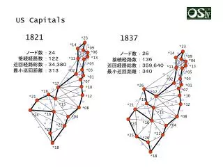
Darcy Law Is Not Enough(In Pore Network) • Viscous Fingering • Invasion Percolation • Diffusion Limited Aggregation • Fractal Characteristics
Research Tools at Pore Scale • Flow Visualization using Glass Micromodel • Pore Network Simulation
Glass Etched Micromodels 1) Preparing the pattern of porous media 2) Elimination of the protection-layer of the mirror 3) Covering the mirror with photo resist laminate 4) Exposing the covered mirror to UV light 5) Elimination of not-lightened parts using a developer 6) Etching the glass with HF 7) Fusing the etched glass with a plain glass
Pores provide volume & interconnectivity Pore throats provide resistance to flow. Mass conservation at each pore: Simple solution to the momentum equations in each pore throat. Pore Network Modeling 1. A discrete view of the porous medium (pores and pore throats) 2. Solution to various transport problems using conservation equations.
Solution of the Fluid Flow in the Network Conductances: Fluid Flow Equations a) One Phase (Oil): b) Two-Phase (Oil & Gas): Nodes with Oil-Gas Front: g =0.5GA2/μ , circular cross section g = 0.5623GA2/μ , square cross section g = 3R2A/20μ , triangular cross section Pgas= Constant= Patm Continuity (Mass Balance) Eq. For Each Oily Node: At = πR2 , circular cross section At = 4R2 , square cross section At =R2/4G , triangular cross section Writing Continuity Eq. for all Nodes, We have a linear set of equations: Film Conductance:
Gas-Oil Displacement Generalization of Continuity Eq. for Different Fluid Configurations 34 Different Fluid Gonfigurations → 34 Different Continuity Equations Example: If All Adjacent Nodes of Node i Are Oily Nodes: Example: If One of the Adjacent Nodes of Node i be Occupied by Gas:
Pore LevelDisplacement Mechanisms • 2-Phase Displacement Mechanisms a) Drainage b) Imbibition c) Counter-Current Drainage 3-Phase Displacement Mechanisms a) Double Drainage b) Double Imbibition
Model Assumptions ≈10-6 → Viscous forces are negligible ≈ 1609 > 10-4 → Gravity forces are very important
Future Work • Micible Co2 Flooding with Gravity Domination Using Glass-etched Micromodel and Pore network Modelling
Miscible Co2 Flooding with Gravity Domination • Establishing Flow Visualization Lab • Performing Miscible Displacement Tests • Developing Pore Network Model for Miscible Displacement • Identifying Controlling parameters • Performing Experimental in Core Scale • Performing Process Optimization • Upscaling
End Any Questions?