Download
1 / 46
470 likes | 740 Views
Programmable Logic Devices by Abdulqadir Alaqeeli 1/27/98. Programmable Logic Programming Methods Programmable Logic Devices SPLDs CPLDs FPGAs Designing for FPGAs Metastability Synchronous Designs Designing State Machine. Programming Methods. FUSE.

E N D
Programmable Logic • Programming Methods • Programmable Logic Devices • SPLDs • CPLDs • FPGAs • Designing for FPGAs • Metastability • Synchronous Designs • Designing State Machine
FUSE • Fuses are the basic storage element in TTL programmable circuits. • Passing a large current through fuse layer blows it. This allows the IC to store data by having the fuses selectively blown.
EPROM • In CMOS the metal fuse is replaced by FAMOS transistor. • By hot electron injection, a charge is placed onto the floating gate and switch action is provided. • UV erasable.
EEPROM and SRAM • EEPROM • Electrically erasable floating gate. • No UV. • SRAM • Loads configuration memory cells that control the logic and interconnect. (i.e. pass-transistors) • To erase, turn the power off.
Programming Technologies 1) Bipolar fusible link - Closed device, burned open by high current 2) SRAM based - Uses pass transistors controlled by SRAM - CMOS based 3) E/EEPROM based - Floating gate - CMOS based
Programmable Logic Devices • Simple PLDs: • PALs • PLAs • PROMs • GALs • Complex PLDs • FPGAs
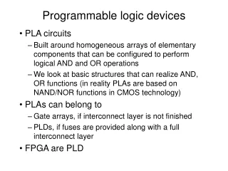
Programmable Array Logic PALs • Programmable AND array. • Fixed OR array. • Bipolar, Fuse. • Large number of Inputs. • Each Output relatively independent.
Programmable Logic Arrays PLAs • Programmable AND array. • Programmable OR array. • Bipolar, Fuse. • Large number of Inputs. • Output functions share some product terms.
Programmable ROMPROM • Fixed AND array. • programmable OR array. • Fuse. • Limited number of Inputs. • Strong independence among the Outputs.
PALs : most popular PLD architecture. • PLAs : most flexible of combinatorial PLDs. • PROMs:can be used to store any logic function.
Generic Array LogicGALs • Configurable PAL-type. • CMOS. • Electrically Erasable CMOS technology • Replaces many PAL devices.
Complex Programmable Logic Devices ( CPLDs )
XC7300 Dual Block Architecture • Universal Interconnect Matrix • - SMARTswitch PAL-like Function Block High Density Function Block High Density Function Block Input Registers I/O I/O UIM 3.3 /5 Volt I/O High Drive - 24 mA Fast Function Block Fast Function Block FO FO FAST tSU = 4.0 ns tC0 = 5.5 ns FAST 5 ns Pin to Pin fCLK =167 MHz
3 JTAG Controller In-System Programming Controller JTAG Port Function Block 1 I/O I/O Function Block 2 I/O I/O Blocks FastCONNECT Switch Matrix I/O Function Block 3 Global Clocks 3 Global Set/Reset 1 Function Block n Global Tri-States 2 or 4 XC9500 - Flexible Architecture
Global Clocks Global Tri-State 2 or 4 3 I/O Macrocell 1 Product- Term Allocator AND Array 36 From FastCONNECT I/O Macrocell 18 To FastCONNECT XC9500 Function Block
XC9500 Architectural Features • Uniform, PAL-like architecture • Flexible function block • 36 inputs with 18 outputs • Expandable to 90 product terms per macrocell • Product term and global 3-state enables • Product term and global clocks • 3.3V/5V I/O operation
XC9500 Optimizes Pin-Locking Add another pin or FB output Add more logic Inputs • 36 • Inputs Fixed Output Pin D/T Q FastCONNECT Switch Matrix Function Block Logic Add another FB input
XC9500 Product Family 0.6µ Phase I Family 9536 9536F 9572 9572F 95108 95108F 95144 95180 95216 95288 Macrocells 36 72 108 144 180 216 288 Usable Gates 800 1600 2400 3200 4000 4800 6400 tPD (ns) 5 7.5 7.5 7.5 10 10 10 Registers 36 72 108 144 180 216 288 Max. User I/Os 34 72 108 133 168 168 192 44PC1 44VQ 84PC1 100TQ 100PQ1 84PC1 100TQ 100PQ1 160PQ1 100PQ 160PQ 208HQ 304HQ 160PQ 208HQ 160PQ 208HQ Packages
Field Programmable Gate Arrays ( FPGAs )
Programmable Interconnect I/O Blocks (IOBs) Configurable Logic Blocks (CLBs) FPGA Architecture
C2 C1 C3 C4 H1 DIN S/R EC S/R Control G4 DIN SD G G3 F' YQ Q D Func. G' G2 H' Gen. G1 EC RD 1 H G' Y Func. H' S/R Gen. Control F4 F F3 DIN SD Func. F' XQ F2 Q D Gen. G' F1 H' EC RD 1 H' X F' K XC4000 Configurable Logic Blocks • 2 Four-input function generators (Look Up Tables) • 16x1 RAM or Logic function • 2 Registers • - Each can be configured as Flip Flop or Latch • - Independent clock polarity • - Synchronous and asynchronous Set/Reset
Combinatorial Logic A B C D Z 0 0 0 0 0 0 0 0 1 0 0 0 1 0 0 0 0 1 1 1 0 1 0 0 1 0 1 0 1 1 . . . 1 1 0 0 0 1 1 0 1 0 1 1 1 0 0 1 1 1 1 1 A B Z C D WE G4 G G3 Func. G2 Gen. G1 Look Up Tables Look Up Table • Combinatorial Logic is stored in 16x1 SRAM Look Up Tables (LUTs) in a CLB • Example: 4-bit address 4 (2 ) 2 = 64K ! • Capacity is limited by number of inputs, not complexity • Choose to use each function generator as 4 input logic (LUT) or as high speed sync.dual port RAM
As Gates As ROM DATA(0)=0 DATA(1)=0 DATA(2)=0 DATA(3)=1 I1 A0 F1 F1 O = I1*I2 X O X DOUT I2 F2 A1 F2 ROM is Equivalent to Logic • When using ROM, it is simply defining logic functions in a look-up table format • Memory might be an easier way to define logic • Xilinx provides ROM library cells • FPGA lookup tables are essentially blocks of RAM • Data is written during configuration • Data is read after configuration • Effectively operate as a ROM
CLB CLB D1 32 bits 2 bits D1 D Q Q1 A0 O1 A1 A2 D2 D Q Q2 A3 A4 CLK WE RAM Provides 16X the Storage of Flip-Flops • 32 bits versus 2 bits of storage • Two 16x1 RAMS or One 32X1 Single Port Ram fit in one CLB • One 16x1 Dual Port RAM fits in one CLB • 32x8 shift register with RAM = 11 CLBs • Using flip-flops, takes 128 CLBs for data alone • Address decoders not included
RAM Guidelines • Less than 32 words is best • 32x1 or 16x2 per RAM requires only one CLB • Delays are short, (one level of logic) • Data and output MUXes are required to expand depth • Less than 256 words recommended per RAM • Use external memory for 256 words or more • Width easily expanded • Connect the address lines to multiple blocks • Recommendation: Use less than 1/2 of max memory resources • Maximum memory uses all logic resources of CLBs
XC4000E I/O Block Diagram Vcc Slew Passive Rate Pull-Up, Control Pull-Down T/OE O D Q Output Pad Buffer OK (Output Clock) I 1 Input I Buffer 2 Q D Delay CE IK (Input Clock) Elements in BLUE are not in the XC3000 family.
CLB CLB Switch Matrix Switch Matrix CLB CLB Xilinx FPGA Routing • Fast Direct Interconnect - CLB to CLB • General Purpose Interconnect - Uses switch matrix • Long Lines • Segmented across chip • Global clocks, lowest skew • 2 Tri-states per CLB for busses
Direct connections from CLB to adjacent CLB or IOB Fastest interconnect Less than 1 ns delay Fast Direct Interconnect CLB CLB CLB CLB
Flexible but slow if crosses many channels XC3000 5 lines per channel XC4000 8 similar Single- Length lines 4 Double-Length lines skip every other switch matrix 4 Quadrable-Length Lines skip three switch matrices. Flexible General-Purpose Interconnect CLB CLB Switch Matrix Switch Matrix CLB CLB
Use Long Lines for High Fanout Nets • Single metal lines that traverse length & width of chip • Lowest skew • Ideal for high fan-out signals • Ideal for clocking • Internal three-state buffers for buses and wide functions CLB CLB CLB CLB
CPLD or FPGA? • FPGA • SRAM reconfiguration • Excellent for computer architecture, DSP, registered designs • PROM required for non-volatile operation • CPLD • Non-volatile • Wide fan-in • Fast counters, state machines • Combinational Logic
Avoiding Metastability • Metastability caused by violation of timing specifications such as setup • In-between state takes unknown time to resolve • Two destinations could be responding to different values • Error rate decreases by a factor of 40 for every additional 1ns of delay before destinations respond to signal • Be aware but not paranoid! D Q Metastable Output Data and Clock Change Simultaneously
Use Synchronous Design • Easy to analyze internal timing of synchronous designs • Hold time is not an issue • Clock skew is guaranteed to be much shorter than the minimum clock-to-Q of any CLB • Use global clock distribution networks • If not, check for clock skew problems 2.5ns D Q D Q 3.0ns 3.1ns
Avoid Gated Clock or Asynchronous Reset • Move gating to non-clock pin to prevent glitch from affecting logic • Or separate input signal changes by at least a CLB delay to minimize the likelihood of a glitch 3-Bit Counter 3-Bit Counter D Q Q0 Q0 Carry Carry-1 Q1 Q1 D Q Q2 Q2
Pipeline for Speed • Register-rich FPGAs encourage pipelining • Pipelining improves speed • Consider wherever latency is not an issue • Use for terminal counts, carry lookahead, etc. • Clock period will be approximately • 2 x (number of combinatorial levels) x (speed grade) • XC3100A-3: 3 levels x 2 x 3ns = 18 ns clock period
Use Dedicated Carry for Large Counters • Use XC4000/XC5000 carry logic to improve counter speed and density • Especially for counters of >5 bits tADDER tCO A d d e r R e g tNET
Use One-Hot Encoding for State Machines • Shift register is always fast and dense • “One-hot” uses one flip-flop for each count • Useful for state machine encoding • Use MooreType state machines. D Q D Q D Q D Q D Q
Use LFSRs for Fixed Count • Consider Linear Feedback Shift Register for speed when terminal count is all that is needed • Or when any regular sequence is acceptable (e.g., FIFO) • Maximal length sequence of 2n-1 • Use XNOR feedback to make lockup state all 1s 10-bit Shift Register D1 Q1 Q7 Q10
Use Global Clock Buffers • Use clock buffers for highest fanout clocks • Drive low-skew, high-speed long line resources • Use BUFG primitive to be family-independent • Limit number of clocks to ease placement issues • XC3000: 2 (GCLK, ACLK) • XC4000/XC5000: 4 (BUFGP / BUFG) • Additional clocks might be routable on long lines • Otherwise routed on general interconnect • Slower and higher skew
Using a Clock Generated Off-Chip • Connect IPAD directly to clock buffer primitive • Required for BUFGP • Provides higher speed and uses fewer routing resources D IPAD BUFG
Generating Clock On-Chip • XC4000 • Internal clock available after configuration • Use OSC4 primitive F8M F500k BUFGS F16k OSC4 F490 F15
Use Clock Enables Instead of Gating Clock • Use clock enable when using most of or all logic inputs • Not recommended to gate clock signal directly • Use muxed data when using only 1-2 logic inputs • Easier to route • Some macros use logic for clock enable while others use the CE pin • Make sure CE, if unused, is always connected to VCC FDxE D Q CE D Q CE