Download
1 / 16
170 likes | 420 Views
ECE 20B: Introduction to Electrical and Computer Engineering Winter 2003 Recitation 1: Operational Amplifiers. Ideal Amplifier. “Amplifies” weak (= low voltage) electrical signals. E.g. Cassette/CD player, strain gauge, accelerometer. Ideal amplifier: Output Signal = Gain x Input Signal

E N D
ECE 20B: Introduction to Electrical andComputer EngineeringWinter 2003Recitation 1: Operational Amplifiers
Ideal Amplifier • “Amplifies” weak (= low voltage) electrical signals. E.g. Cassette/CD player, strain gauge, accelerometer. • Ideal amplifier: Output Signal = Gain x Input Signal • Ideal amplifier: has infinite input resistance, zero output resistance. - Infinite input resistance: Does not load input signal - ZeroOutput resistance: Does not “eat up” output signal • Gain of ideal amplifier A = Voutput/Vinput
Ideal Amplifier…contd. • Schematic of amplifier RS Rout + vS + Rin + + vin Avin vL RL - - - - • (Figure 12.3) Rin = equivalent resistance seen at input of amplifier; Rout = internal (output) resistance of amplifier • vin = (Rin / (RS + Rin)) vS • vL = Avin (RL / (Rout + RL)) = vin [A(RL / (Rout + RL)) (Rin / (RS + Rin))] vS
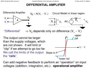
+V positive power supply Inverting input _ Vout + Non-inverting input -V negative power supply Operational Amplifiers • Op-amp: 4 inputs, 1 output Output goes positive when non-inverting input (+) goes more positive than the inverting input (-), and vice-versa. • Vout = AV(OL) (v+ - v-) • Amplification factor, or gain, AV(OL) is called the open-loop voltage gain; typically O(105 – 107) • Open-loop assumption (Rizzoni Eq. 12.10): iin = 0 (“Golden Rule #2: The inputs of an op-amp draw no current.” – cf. Horowitz and Hill textbook)
Operational Amplifier…contd. • Consider some typical values: • Ri = 105 – 1012 Ohms • Ro = 1 – 50 Ohms • A = 105 – 107 V/V • Suppose A = 105 , +V = 12V, -V = -12V • 120uV achieves saturation (output voltage cannot exceed supply) • Current into input terminals is 120uV / 105 Ohms = 120 x 10–11 A (open circuit) • Rout is low, approximated as 0 • Vout = A(v+ - v-) • How does op-amp output vary with A when v- is sinusoidal? • A continuous sinusoid generates a square wave as output
Square wave output • For a sinusoid, the output of Op-amp is a square wave with only two distinct voltage levels –1V and +1V • We can represent the voltage levels as ‘0’ (= -1V) and ‘1’ (= +1v). • Op-amp is a primitive digital element
Op-amp comparator • In comparator configuration of Op-amp, the inverting input is connected to ground and input is given in non-inverting input. • If the input signal is slightly positive, then the output jumps to V+ ( = supply voltage) • If the input signal is slightly negative, then the output jumps to V- (= - supply voltage) • The output jumps between two extremes V+ and V- since the open-loop gain is very high.
Op-amp – Digital output in open loop mode • Output of comparator in open-loop mode Source: http://www.tonmeister.ca/main/textbook/electronics/12.html
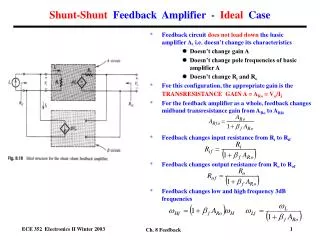
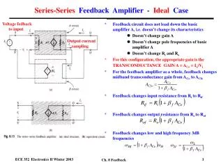
Feedback • Negative feedback: process of coupling the output back in such a way as to cancel some of the input • Lowers gain, but amplifier characteristics become less dependent on characteristics of the open-loop (no-feedback) amplifier; eventually depend only on properties of the feedback network itself • A “self-balancing mechanism” that allows amplifier to preserve zero potential difference between its input terminals • Feedback can also be positive (oscillators, etc.) • Observe: voltage gain is so high that a tiny voltage between input terminals will swing the output over its entire range • Ignore this small voltage “Golden Rule #1: The output attempts to do whatever is necessary to make the voltage between the inputs zero.”
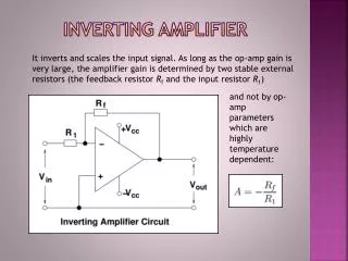
R2 R1 A in B Inverting (gain = negative) Amplifier • Point B is at ground Point A is also (G.R. #2) • voltage across R2 is Vout , and voltage across R1 is Vin • G.R. #1 across R2 is Vout / R2 = - Vin / R1 • Voltage gain = across R2 is Vout / Vin = - R2 / R1
Non-Inverting (gain = positive) Amplifier • VA comes from a voltage divider VA = VoutR1 / (R1 + R2) • G.R. #2 VA = Vin • Gain = Vout / Vin = 1 + R2 / R1
Voltage follower • Output voltage follows input voltage. • Gain = 1 since feedback resistance R2 = 0 • Is used as a buffer to isolate input signal from output
Mixer amplifier • A mixer amplifier mixes several input signals and amplifies them at various levels • Inputs from several sources are connected to the inverting input of the Op-amp as shown • The gain can be varied by modifying the series resistances • The total voltage at the output will be Vout = -(v1 (Rf/R1) + v2 (Rf/R2))
Op-amp oscillators • An Op-amp with a positive feedback produces an oscillator • An oscillator produces output voltage without any input signal • Positive feedback refers to the case where output is fed back to the input such that it augments the input signal • The Op-amp circuit with a single R and C produces a square wave output with a frequency of 1/(2RC)
Op-amp oscillators…contd • RC phase-shift oscillators are used to produce sinusoidal outputs • A RC network is used in the positive feedback loop to shift phase by desired amount • A simple sinusoidal oscillator shown below consists of three CR ladders cascaded and given to inverting input of Op-amp +V C1 C2 C3 - vout + R2 R3 R1 -V
Op-amp summary Source: http://hyperphysics.phy-astr.gsu.edu/hbase/electronic/Op-ampcon.html