Download
1 / 24
240 likes | 259 Views
Explore system architecture, memory setup, VHDL truth tables, and project creation in this hands-on lab session. Learn about program counters, registers, and control logic. Visit the link for detailed instructions.

E N D
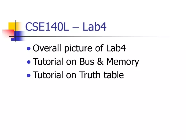
CSE140L – Lab4 • Overall picture of Lab4 • Tutorial on Bus & Memory • Tutorial on Truth table
CSE140L – Lab4 • A simple computer system with a minimal instruction set. • Load/store data • Addition • Shift • Compare • Mask
CLK Pencil & Paper Register Profile RST Marker CSE140L – Lab4 • System architecture Program Counter Calculator Datapath Control Logic Memory (instructions) You Task List
CSE140L – Lab4 • Function of each module • Program counter: mark the current instruction • Memory: hold instructions • Datapath: compute results • Registers: hold data • Control logic: compile instructions to actions.
CSE140L – Lab4 • Overall picture of Lab4 • A system design including register profile, datapath, memory, program counter and control logic. • http://www.cse.ucsd.edu/classes/sp05/cse140L/lab/lab4/lab4.htm
CSE140L – Lab4 • Tutorial on Bus & Memory • Build a 16x4bit memory block • Memory Elements:(http://www.cse.ucsd.edu/classes/sp05/cse140L/lab/lab2/lib.pdf) • RAM (Writable) • ROM (Read-only) ROM16x1
CSE140L – Lab4 • ROM16x1 INIT The data output (O) reflects the bit selected by the 4-bit address (A3 – A0). The ROM is initialized to a known value during configuration with the INIT=value parameter. 0110101100001111 O A0A1A2A3
CSE140L – Lab4 • 16x4 memory block addr(3:0) data(3:0)
CSE140L – Lab4 • 16x4 memory block initialize
CSE140L – Lab4 • Tutorial • Create a project memblk • Add a schematic diagram memblk to the project • Create I/O markersMenu Tools Create I/O Markers
CSE140L – Lab4 You will see two I/O buses on the canvas • Place 4 ROM16x1 modules • Extend two I/O buses beforeand after the ROM modulesby using “add wire” button (You will see thicker wires)
CSE140L – Lab4 • Add bus taps by using “Add Bus Tap” button.You can change the direction of by selecting the orientation in the options window.
CSE140L – Lab4 • Connect the taps to module pins by wire
CSE140L – Lab4 • Click on “Add Net Name”Then type the net name in the options window.Now you will see the name appear after the cursor. • Click on the wire you want to name.
CSE140L – Lab4 • Name all the nets • Double click on a ROM module, the property window will pop up. Change the INIT value and make it visible.
CSE140L – Lab4 • Click OK. You will see the initial value appears. • Change the initial values for other ROM modules and save the diagram.
CSE140L – Lab4 • Create a symbol for the memory block.
CSE140L – Lab4 • Tutorial on VHDL Truth Table
CSE140L – Lab4 • Tutorial • Create a project truthtbl • Add a VHDL Module truthtbl to the project
CSE140L – Lab4 You will see a template library IEEE; use IEEE.STD_LOGIC_1164.ALL; use IEEE.STD_LOGIC_ARITH.ALL; use IEEE.STD_LOGIC_UNSIGNED.ALL; ---- Uncomment the following library declaration if instantiating ---- any Xilinx primitives in this code. --library UNISIM; --use UNISIM.VComponents.all; entity truthtbl is end truthtbl; architecture Behavioral of truthtbl is begin end Behavioral;
CSE140L – Lab4 • Add the following port declaration into the entity declaration. • Add the following code to the architecture part. entity truthtbl is PORT (A :IN STD_LOGIC_VECTOR(2 DOWNTO 0); D : OUT STD_LOGIC_VECTOR(1 DOWNTO 0) ); end truthtbl; architecture Behavioral of truthtbl is begin process (A) begin if (A(2 downto 0)="000") then D(1 downto 0) <= "01"; end if;
CSE140L – Lab4 if (A(2 downto 0)="001") then D(1 downto 0) <= "11"; end if; if (A(2 downto 0)="010") then D(1 downto 0) <= "10"; end if; if (A(2 downto 0)="011") then D(1 downto 0) <= "10"; end if; if (A(2 downto 0)="100") then D(1 downto 0) <= "10"; end if; if (A(2 downto 0)="101") then D(1 downto 0) <= "01"; end if; if (A(2 downto 0)="110") then D(1 downto 0) <= "11"; end if;
CSE140L – Lab4 if (A(2 downto 0)="111") then D(1 downto 0) <= "00"; end if; end process; end Behavioral; • Save the VHDL file. • Click on the VHDL file in the Sources window
CSE140L – Lab4 • Under the Design Utilities category in Process View, double click on Create Schematic Symbol • Now the truth table has been implemented and can be used in top level schematic diagram.