Download
1 / 59
620 likes | 727 Views
Ethernet over SONET. Dr. John S. Graham University of London Computer Centre. Ethernet vs SONET. DXC. MUX. MUX. R. R. Section Layer. Section Layer. Section Layer. Section Layer. Line Layer. Line Layer. Path Layer Connection. SONET/SDH Model. SONET Network Elements. 1. 4. 30.

E N D
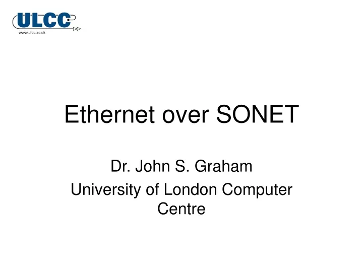
Ethernet over SONET Dr. John S. Graham University of London Computer Centre
DXC MUX MUX R R Section Layer Section Layer Section Layer Section Layer Line Layer Line Layer Path Layer Connection SONET/SDH Model
1 4 30 59 90 Section SPE Path 3 PTR Line 5 86 columns SONET STS-1 Frame Payload Capacity = 756 Bytes = 48.384 Mb/s
Section FramingA1 FramingA2 STS-1 ID C1 BIP-8 B1 Orderwire E1 User F1 Data Com D1 Data Com D2 Data Com D3 Section Overhead Bytes
BIP-8 B2 APS K1 APS K2 Data Com D4 Data Com D5 Data Com D6 Data Com D7 Data Com D8 Data Com D9 Data Com D10 Data Com D11 Data Com D12 Line Sync Stat Z1 Line FEBE Z2 Orderwire E2 Line Overhead Bytes
Path Trace J1 BIP-8 B3 Signal Label C2 Path Path Status G1 User Channel F2 Multi-frame H4 Path Overhead Bytes
Accurate Bit-Level Timing • Line Coding • AMI, AMI RZ • HDB3 • Block Coding • 4B/5B (FDDI) • 5B/6B (E3) • 8B/10B (Gigabit Ethernet) • Scrambling • Frame Synchronous • Self Synchronous
8B/10B Encoding (1/2) • Ensures equal number of 1’s and 0’s for • Clock recovery • DC Balance • Detection of single bit transmission errors • Predefined ‘comma’ (0011111 and 1100000) characters
8B/10B Encoding (2/2) • Data (D) and commands (K) encoded separately • Octet split into 5 MSB and 3 LSB • Code groups generated from lookup tables D2.0
Scrambling in SONET/SDH SDH STM-1 uses x7 + x6 +1 polynomial
Concatenation STS-3 155 Mb/s 145.152 Mb/s STS-3c/VC-4 155 Mb/s 149.76 Mb/s STS-12 622 Mb/s580.608 Mb/s VC-4-4 622 Mb/s599 Mb/s STS-12c 622 Mb/s 599.04 Mb/s
1 A 3 - 5 ??? B F 1 – 12 (622 Mb/s) C E 7 10 -12 D 9 Provisioning Example
Bandwidth Fragmentation Drop Interface (Node F) STS-3c Blocked! STS-12 Ring
Virtual Concatenation Drop Interface (Node F) STS-3c STS-1-3v Ring STS-12
Differential Delay Core Network(Partial Mesh) Source STS-1-12v Sink Ty TX
11 1 2 3 4 5 6 12 7 10 9 8 GID-a, SQ#=2 GID-a, SQ#=1 GID-b, SQ#=3 GID-b, SQ#=2 GID-a, SQ#=0 GID-b, SQ#=1 GID-a, SQ#=3 VCAT Example STS-1-4v STS-1-3v STS-12
VCAT Puzzle • An STS-1-2v between Chicago and London • One STS-1 sent via geostationary satellite • The other STS-1 sent via transatlantic fibre • Will it work? ;-)
Link Capacity Adjustment Scheme • Modify membership of a VCG • On-demand and hitless bandwidth changes • Automatic removal of failed VCG members • Interworking of LCAS-enabled VCG with non-LCAS VCG • Old-style ‘bridge and roll’ requires double bandwidth
LCAS Messaging • Member Status (MST) • Re-Sequence Acknowledge (RS-Ack) • Control (CTRL) • Fixed • Add • Norm • EOS • Idle • DNU • Group ID • CRC
CTRL = NORM SQ = 1 CTRL = EOS SQ = 2 CTRL = IDLE SQ = 255 CTRL = NORM SQ = 1 CTRL = EOS SQ = 2 CTRL = ADD SQ = 255 CTRL = NORM SQ = 1 CTRL = EOS SQ = 2 CTRL = NORM SQ = 1 CTRL = NORM SQ = 2 CTRL = EOS SQ = 3 MST = OK (#3) CTRL = NORM SQ = 1 CTRL = NORM SQ = 2 CTRL = EOS SQ = 3 RS-ACK Source PTE STS-1 #1 STS-1 #2 STS-1 #3 LCAS Signalling Flows (1/3) MST = FAIL (#3)
CTRL = NORM SQ = 1 CTRL = NORM SQ = 2 CTRL = EOS SQ = 3 CTRL = IDLE SQ = 255 CTRL = NORM SQ = 2 CTRL = EOS SQ = 3 CTRL = NORM SQ = 1 CTRL = EOS SQ = 2 MST = FAIL (#1) CTRL = NORM SQ = 1 CTRL = EOS SQ = 2 RS-ACK Source PTE STS-1 #1 STS-1 #2 STS-1 #3 LCAS Signalling Flows (2/3)
CTRL = NORM SQ = 1 CTRL = NORM SQ = 2 CTRL = EOS SQ = 3 CTRL = NORM SQ = 2 CTRL = IDLE SQ = 255 CTRL = NORM SQ = 1 CTRL = EOS SQ = 2 MST = FAIL (#3) CTRL = NORM SQ = 1 CTRL = EOS SQ = 2 RS-ACK Source PTE STS-1 #1 STS-1 #2 STS-1 #3 LCAS Signalling Flows (3/3) CTRL = NORM SQ = 1
IEEE 802.2 LLC IEEE 802.2 LLC FC-4 Upper Layer Mapping IEE 802.3 MAC IEEE 802.3 CSMA/CD FC-3 Common Services IEEE 802.3 PHY PCS FC-2 Signalling PMA FC-1 Encode/Decode PMD FC-0 Interface & Media MDL Gigabit Ethernet (802.3z) ANSI X3T11 Fibre Channel IEEE 802.3 Ethernet IEEE 802.3z Gigabit Ethernet
Sequence of Events LINK_NOT_AVAILABLE ~ LINK_NOT_AVAILABLE LINK_CONFIGURATION ~ LINK_CONFIGURATION IDLE ~ IDLE SOP PREAMBLE SFD DA SA LENGTH LLC Data PADDING FCS
Generic Framing Procedure • ITU-T G.7041 and ANSI T1.105.02 • Defines mapping for many types of service onto SONET/SDH or OTN: • Ethernet, IP/PPP • GbE, Fibre Channel (inc. DVB), FICON etc • Excellent bandwidth utilization; efficiency tailored to suit different client types • Simple delineation and robust error control • Extensible
Motivation for GFP (1/2) • ATM • Cell overhead causes 10% bandwidth inflation • Adaptation functions needlessly complex • Packet over SONET (POS) • Requires all frames to be converted to PPP over HDLC • Byte stuffing causes non-deterministic bandwidth inflation • QoS hard to monitor or guarantee
Motivation for GFP (2/2) • Minimal overhead • Transport of client PDUs in native format • Designed for optimized processing • Easy aggregation of frames from multiple client and multiple protocols into shared bandwidth channels • Low latency capabilities for SAN
GFP Client Frames Control Frames Data Frames Management Frames Idle Frames OA&M Frames GFP: Types of Frame
GFP: Functional Model Source = IEEE Communications Magazine, May 2002
GFP: Frame Structure Source = IEEE Communications Magazine, May 2002
GFP: Client-Independent Processes • Synchronization • Bit Level • Frame Delineation • Scrambling • Multiplexing • GFP Frame • Client PDU
No CHEC Match cHEC Match Hunt Presync No 2nd cHEC Match cHEC Mismatch 2nd cHEC Match Sync cHEC Match GFP: Synchronization
PLI cHEC Payload PLI cHEC Payload PLI cHEC Payload PLI cHEC Payload PLI cHEC Payload PLI cHEC Payload GFP: Frame Delineation
STS-3c-2v 1 1 GFP Framer GFP Framer 2 2 3 3 1 2 3 GFP: Client PDU Multiplexing Source Sink
PLI (MSB) PLI (LSB) 7 cHEC (MSB 1 Preamble cHEC (LSB) 6 SFD Payload Header 6 Destination Payload 2 Source Length Data 4 FCS FCS GFP-F Encapsulation (1/2) Ethernet MAC Frame X = 4 to 64 Transmission Order 0 to 65,535 - X 4 1 8 Bit Transmission Order
PLI (MSB) PLI (LSB) PPP/HDLC Frame cHEC (MSB Flag (0x7E) 1 X = 4 to 64 cHEC (LSB) Address Transmission Order 1 Payload Header Control 1 Payload 0 to 65,535 - X PPP Type 2 Data FCS 4 4 1 8 FCS Bit Transmission Order GFP-F Encapsulation (2/2)
Octet Number 000 001 010 011 100 101 110 111 65B Sequence 1 1 001 C1 0 101 C2 D1 D2 D3 D4 D5 D6 GFP-T: 64B/65B Payload 64B Sequence D1 K1 D2 D3 D4 K2 D5 D6 Octet Number F 000 001 010 011 100 101 110 111
GFP-T Error Detection • Leading flag bit is errored • Error affects ‘Last control-code’ indicator • Control-code location address received in error • Error causes 4-bit control code to be modified
1,1 1,2 … 1,7 1,8 1,1 8,1 1,2 8,2 … … 8,1 8,2 … 8,7 8,8 1,7 8,7 1,8 8,8 CRC (MSB) CRC (LSB) GFP-T: Superblocks 536-bit Byte-Aligned
Pros and Cons: GFP-F • Higher bandwidth efficiency • Higher Latency • More buffer memory required • Core header fields must be calculated


![IP over Ethernet over 802.16 [draft-ietf-16ng-ip-over-ethernet-over-802.16-02.txt]](https://cdn1.slideserve.com/1767813/ip-over-ethernet-over-802-16-draft-ietf-16ng-ip-over-ethernet-over-802-16-02-txt-dt.jpg)


![IP over Ethernet over 802.16 [draft-ietf-16ng-ip-over-ethernet-over-802.16-05.txt]](https://cdn2.slideserve.com/4152768/ip-over-ethernet-over-802-16-draft-ietf-16ng-ip-over-ethernet-over-802-16-05-txt-dt.jpg)