Download
1 / 21
250 likes | 586 Views
8051 Timers. Since this is a microcontroller it mainly finds itself in embedded devices Quite often embedded devices need to synchronize events The way this is done is via time We could do it by inserting a loop or a bunch of NOP commands Is this accurate?

E N D
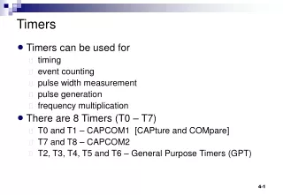
8051 Timers • Since this is a microcontroller it mainly finds itself in embedded devices • Quite often embedded devices need to synchronize events • The way this is done is via time • We could do it by inserting a loop or a bunch of NOP commands • Is this accurate? • A better way to do it is to use timers • Basically an internal stop watch • The 8051 has two timers CSC321
Timers and Interrupts 8051 implementation CSC321
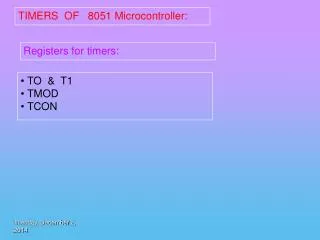
Using the timers • Controlled through two special function registers (SFR) • TMOD – configure the timers • TCON – control the timers CSC321
TMOD CSC321
Timer Modes • Modes 1 and 2 are the most common • Mode 1: 16-bit timer, sets overflow when complete • Mode 2: 8-bit timer, reloads and sets overflow when complete CSC321
TCON • Bits 5 and 7 are the overflow bits for each timer and are set by hardware • Bits 4 and 6 turn the timers on/off • More on bits 0-3 later CSC321
Timer control • Setting bits TR0 and TR1 (setb TR0 and setb TR1 instructions) start the timers • Clearing bits TR0 and TR1 (clr TR0 and clr TR1 instructions) stop the timers CSC321
Reading the timers • If the timers are stopped, reading is trivial mov R6, TL0 mov R7, TH0 • If the timers are running, it gets tricky try: mov A, TH0 mov R6, TL0 cjne A, TH0, try mov R7, A We don’t want TH0 to roll over while we are reading TL0 CSC321
Programming the timer (part 1) ; set timer 0 to 8-bit mode mov TMOD, #0x02 ; start value mov TL0, #0x00 ; reset value when ; the timer hits 0xFF mov TH0, #0x00 ; start timer 0 setb TR0 ; kill some time nop nop nop nop nop CSC321
Programming the timer (part 2) ; stop timer 0 clr TR0 tryagain: ; read the high byte of the timer mov A, TH0 ; read the low byte of the timer mov R6, TL0 ; read the high byte again to make sure it didn't change ; while we were reading the low byte cjne A, TH0, tryagain ; keep the high byte if it didn't change mov R7, A ; the full 16-bit timer is now in R7/R6 CSC321
8051 Interrupts • A signal to let the CPU know that something out of the ordinary flow of instructions has occurred • Various sources of interrupts in the 8051 • Two external • Two internal (timers) • I/O (serial port) CSC321
Set up by the TCON register • The bits we didn’t talk about previously CSC321
When an interrupt occurs • Current instruction is allowed to complete • Program counter (PC register) is saved on the stack (SP) • Address of the interrupt service routine (ISR) is loaded to the program counter CSC321
Interrupt service routine • Also known as an interrupt vector • The 8051 has six of them • Usually the ISR is nothing more than a JMP to the actual subroutine (due to lack of space between interrupt vectors) CSC321
Enabling/Disabling interrupts • To use an interrupt you must first enable it • They are disabled by default (power up) • Enabling is a 2 step process • First enable all interrupts – setb EA • Then enable individual interrupts – setb ET0 • See next slide for why 2 steps… CSC321
Why two steps? • Because it makes turning them on and off very easy • Consider a critical section of code (more than 1 instruction) • You don’t want it to be interrupted • but you don’t want to turn off a bunch of interrupts knowing you’ll have to turn them back on (that takes time) • Using clr EA and setb EA does the trick in the shortest time possible CSC321
There is a little bit more… • Since the interrupt vectors are in low address memory (see table) you can’t put your main program there • Address 0 is the default program memory address • The 8051 assembler provides a solution org address • Provides a way to force code to a particular address – it’s not an instruction, but a directive CSC321
Programming interrupts (part 1) • Setting up the ISR ; org tells the assembler where to place the code org 0 ; start at the main program label jmp main ; timer 0 ISR is at address 0x000B org 0x000B ; obviously not a good ISR but it makes the point timer0: jmp timer0 reti CSC321
Programming interrupts (part 1) • The main program (almost the same as before) ; start the main program at address 0x0030 org 0x0030 main: ; set timer 0 to 8-bit mode mov TMOD, #0x02 ; start value mov TL0, #0xFC ; reset value when ; the timer hits 0xFF mov TH0, #0x00 ; enable interrupts setb EA setb ET0 CSC321
Programming interrupts (part 2) • more main program (same as before) ; start timer 0 setb TR0 ; kill some time nop nop nop nop nop ; stop timer 0 ;clr TR0 CSC321
Programming interrupts (part 3) • more main program (same as before) tryagain: ; read the high byte of the timer mov A, TH0 ; read the low byte of the timer mov R6, TL0 ; read the high byte again to make sure it didn't change ; while we were reading the low byte cjne A, TH0, tryagain ; keep the high byte if it didn't change mov R7, A ; the full 16-bit timer is now in R7/R6 CSC321