Download
1 / 73
790 likes | 1.17k Views
Hoang Huu Hanh, PhD hhhanh @ hueuni.edu.vn. UML Unified MODELING Language. based on online courses and presentations. DEFINITION. Unified Modeling Language is the successor to the wave of Object-Oriented Analysis and Design methods that appear in the late `80s and early `90s.

E N D
Hoang Huu Hanh, PhD hhhanh@hueuni.edu.vn UMLUnified MODELING Language based on online courses and presentations
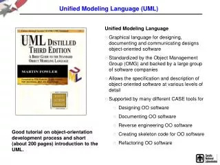
DEFINITION • Unified Modeling Language is the successor to the wave of Object-Oriented Analysis and Design methods that appear in the late `80s and early `90s. • Most directly unifies the methods of Booch, Rumbaugh (OMT), and Jacobson, but its reach is wider than that. • UML went through a standardization process with the OMG (Object Management Group) and is now an OMG standard. Introduction to UML
UML History Introduction to UML
WHAT IT IS • UML is a modeling language, not a method • Most methods consist, at least in principle, of both a modeling language and a process. • Modelling Language is the (mainly graphical) notation that methods use to express designs. • Process is their advice on what steps to take in doing a design. • Modeling Language is the most important part of the method, which is the key part of communication. Introduction to UML
WHY USE UML • Helps Analysis and Design • Used for communication • Use the advantages of OO • Documentation As stated in The Unified Modeling Language User Guide; UML is a language for: • Visualizing • Specifying • Constructing • Documenting Introduction to UML
Visualizing • It makes it easier to understand and work through problem • Since it is a formal language, it enables other developers familiar with the language to more easily interpret our drawings. Introduction to UML
Specifying • We must communicate our software system using some common, precise, and unambiguous communication mechanism. • Again the formal nature of the UML facilitates this specification quite nicely. Introduction to UML
Constructing • We know that the UML is a formal language with its own set of syntactical rules. • Because of this formality, we can create tools that interpret our models. • They can map the elements to a programming language, such as Java, C++. • Many tools such as Rational Rose, supports this forward engineering. In fact this is one of the advantages of using a formal modeling tool. Introduction to UML
Documenting • The models we create are just one of the articats produced throughout the development lifecycle. • Using the UML in a consistent fashion produces a set of documentation that can serve as a blueprint of our system. Introduction to UML
USAGES • Define the boundaries of a system & its major functions • use cases and actors • Illustrate use cases • interaction diagrams • Define the static structure of a system • class diagrams • Model the behavior of objects • state transition diagrams • Document the physical implementation architecture • component & deployment diagrams • Provide for growth • stereotypes Introduction to UML
FUNDAMENTAL UML • Models and Views • Core Diagrams • Fundamental Elements Introduction to UML
Models and Views • UML is more than disjointed diagrams • Turn attention to an illustration of the UML from three different perspectives • Further insight into these divisions enables us to realize one of the greatest benefits of modeling, which is creating different views of our software system. Introduction to UML
Core Elements Introduction to UML
Core Elements (cont’d) ¹ An extension mechanism useful for specifying structural elements. Introduction to UML
DIAGRAMS • Individual diagrams contribute more to the specification of a software system. • They are composition of many of the fundamental elements. • Are mechanism that developers use to communicate and solve problems in the complex aspects of the system. • The most common diagram is the Class Diagram, which describe the structural relationships that exist among the classes, can guide developers in understanding our software system’s class structure. Introduction to UML
VIEWS • As we become more proficient in modeling, we begin to realize that using a combination of diagrams to communicate is most effective. • We may need to combine class diagram with a diagram whose intent is to give systems dynamics. • By combining these called views. • View is a depiction of our system from a particular perspective. • By making different views, we can represent our system from different perspectives. Introduction to UML
VIEWS (cont’d) • There are five main views, • Use case • Design • Development • Process • Physical • They must be consistent with each other, because all of them are representing the same system. • Can be used to validate each other. Introduction to UML
USE CASE VIEW • This view documents the system from the customer’s perspective. • Terminology used in this view should be domain specific. • Depending on the technical nature of our audience, we should avoid obscure technical terms. • Diagrams most common in this view are the use case diagrams and, less common, activity diagrams. • Organizations transitioning to the UML may wish to work only with use case diagrams early and experiment with activity diagrams over time. Introduction to UML
Design VIEW • This view documents the system from designer’sand architect’s perspective. • Diagrams most commonin this view are class and interaction diagrams(either sequence or collaboration), as wellas package diagrams illustrating the packagestructure of our Java application. Introduction to UML
Development VIEW • This view documents the components that thesystem is composed of. • This view typically containscomponent diagrams. • Except for the mostcomplex Javaapplications, this view isoptional. Introduction to UML
Process VIEW • This view documents the processes and threadsthat compose our application. • These processesand threads typically are captured on class diagramsusing an active class. • Because of theadvanced nature of active classes, coupled withthe volume of use, active classes are beyond thescope of this discussion. Introduction to UML
Physical VIEW • This view documents the system topology. • Deployment diagrams that compose this viewillustrate the physical nodes and devices thatmake up the application, as well as theconnectionsthat exist between them. Introduction to UML
VIEWS (cont.) • We are not limited with the listed views. • If there is something that architecturally important, for example security, then we may create a new view (ex: security view) into the system from that perspective. Introduction to UML
Modeling Elements • Structural elements • class, interface, collaboration, use case, active class, component, node • Behavioral elements • interaction, state machine • Grouping elements • package, subsystem • Other elements • note Introduction to UML
Diagrams - The foundation of UML • Use Case Diagrams • Requirements • Activity Diagrams • Generally what, not who - good to detect parallelism • Interaction Diagrams • Collaboration/Communication Diagrams (object centered) • Sequence Diagrams (timeline) • Static Structure Diagrams • Objects/Classes/Packages • Statechart Diagrams • States of objects with interesting lifecycles • Implementation Diagrams • Component Diagrams • Deployment Diagrams Introduction to UML
DIAGRAMS • As we’ve seen, we can combine diagrams that form models and that can serve asviews into our system. • If an advantage in modeling is to combine diagrams to form views into oursystem, then it only makes sense that each diagram has a different focus on whatit communicates. • Each falls into one of two categories: behavioral, and structural. • Most commonly used are use case, sequence, and class diagrams. Introduction to UML
Behavioral diagrams • Behavioral diagrams depict the dynamic aspects of our system.They are most useful for specifying the collaborations among elements that satisfythe behavior of our system’s requirements. • Five diagrams that fall into this category are; • Use case • Activity • State • Sequence • Collaboration (Communication) • Mostly used are use case, sequence, and collaboration. • Activity and state diagrams are used on an as-needed basis. • Activity diagrams visually represent behaviors captured by usecases. • State diagrams, on the other hand, are used to illustrate complextransitionsin behavior for a single class. Introduction to UML
Core Relationships Introduction to UML
Core Relationships (cont’d) Introduction to UML
ScheduleAlgorithm RegistrationForm RegistrationManager addStudent(Course, StudentInfo) Course name numberCredits Student open() name addStudent(StudentInfo) major Professor CourseOffering name tenureStatus location open() addStudent(StudentInfo) Relationships Introduction to UML
Associations Introduction to UML
Association Ends Introduction to UML
Relationship Notation • 1 - one and only one • 4 - four and only 4 • 0..1 - zero or 1 • 5..10 - five to and including 10 • 0..* - zero or more • 4..* - four or more Introduction to UML
Composition Introduction to UML
Generalization Introduction to UML
Generalization Introduction to UML
Dependencies Introduction to UML
Dependencies Introduction to UML
Derived Attributes and Associations Introduction to UML
Links Introduction to UML
Constraints and Comments Introduction to UML
Actors • An actor is someone or some thing that interacts with the system • External Forces • Human interaction • Automated System Traffic Control System Driver Keyboard Operator User <<Backup System>> <<toll booth>> Introduction to UML
Use Cases • A use case is a pattern of behavior the system exhibits • Each use case is a sequence of related transactions performed by an actor and the system in a dialogue • Details what the system must provide to the actor when the use cases is executed • A flow of events document is created for each use case • Written from an actor point of view • Actors are examined to determine their how they interact with the system • Break down into the most atomic actions possible • Typical contents • How the use case starts and ends • Normal flow of events • Alternate flow of events • Exceptional flow of events Introduction to UML
Use Case Diagram • Captures system functionality as seen by users • Built in early stages of development • Purpose • Specify the context of a system • Capture the requirements of a system • Validate a system’s architecture • Drive implementation and generate test cases • Developed by analysts and domain experts Introduction to UML
Use Case Diagram • Use case diagrams are created to visualize the relationships between actors and use cases Pay toll Driver Passager Lost Luggage Customer Service Agent Ramp Maintenance Mechanic Introduction to UML
Use Case Diagram • Captures system functionality as seen by users Introduction to UML
Collaboration Diagrams • A type of interaction diagram that describes theorganizational layout of the objects that sendand receive messages. • Semantically equivalent toa sequence diagram. • It uses class diagrams layout, and can be used to make more cohesive and less coupled classes. Introduction to UML
Collaboration Diagram • A collaboration diagram displays object interactions organized around objects and their links to one another course form : 1: set course info CourseForm 2: process 3: add course : Registrar theManager : aCourse : CurriculumManager Course Introduction to UML 4: new course
Sequence Diagrams • Semantically equivalent to a collaboration diagram. • sequence diagram is a type of interactiondiagram that describes time ordering of messagessent between objects. • Almost in all software development activity, this diagram is used. Introduction to UML