Download
1 / 44
460 likes | 628 Views
ERT 249 C omputer Aided Design (CAD) For Biosystem Engineering. Prepared By: Samera binti Samsuddin Sah Email: samera@unimap.edu.my Phone: 04-9798835/016-4144537. Learning Outcomes. Assessment and Grading. History. Evolution of CAD. Introduction. Engineering Drawing.

E N D
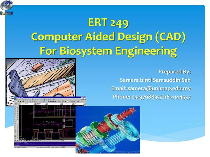
ERT 249ComputerAided Design (CAD)For Biosystem Engineering Prepared By: SamerabintiSamsuddinSah Email: samera@unimap.edu.my Phone: 04-9798835/016-4144537
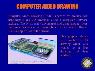
CAD Tools in design process Computer Aided Design The integration of computer software and geometric model to serve the design process
Advantages of CAD 1. 2. 3. 4.
Full name Country Code USA American National Standard Institute ANSI มอก. Thailand สำนักงานมาตรฐานผลิตภัณฑ์อุตสาหกรรม Japanese Industrial Standard Japan JIS British Standard UK BS Australian Standard Australia AS Deutsches Institut fürNormung Germany DIN International Standards Organization ISO Standard Code
Continuous thick line Visible line Dimension line Extension line Leader line Continuous thin line Dash thick line Hidden line Chain thin line Center line Basic Line Types Name according to application Types of Lines Appearance
Meaning of Lines Visible lines represent features that can be seen in the current view Hidden lines represent features that can not be seen in the current view Center linerepresents symmetry, path of motion, centers of circles, axis of axisymmetrical parts Dimension and Extension linesindicate the sizes and location of features on a drawing
Line Convention Precedence of coincide lines. Hidden line drawing. Center line drawing.
Precedence of Line Order of importance Visible line Hidden line Center line
Hidden Line Practice Hidden line should join a visible line, except itextended from the visible line. Leave space Correct Join No !
Hidden Line Practice Hidden line should join a visible line, except itextended from the visible line. Leave space Leave space Correct No !
Hidden Line Practice Hidden line should intersect to form L and Tcorners. L Correct T No !
Hidden Line Practice Hidden arcs should start on a center line.
Centre Line Practice In circular view, short dash should cross at the intersections of center line. For small hole, center line is presented as thin continuous line. Center line should not extend between views. Leave space Leave space
Leave the gap when centerline forms a continuation with a visible or hidden line Center line should always start and end with long dash. Leavespace Leavespace Leavespace Leavespace Centre Line Practice
Drawing Sheet A4 • Trimmed paper of a size A0 ~ A4. A3 A2 • Standard sheet size(JIS) • A4 210 x 297 • A3 297 x 420 • A2 420 x 594 • A1 594 x 841 • A0 841 x 1189 A1 A0 (Dimensions in millimeters)
c d d c c Sheet size c (mm) d (mm) A4 10 25 A3 10 25 A2 10 25 A1 20 25 A0 20 25 Orientation of drawing sheet 1. Type X (A0~A4) 2. Type Y (A4 only) Drawing space Drawing space Border lines Title block Title block