Download
1 / 16
400 likes | 1.15k Views
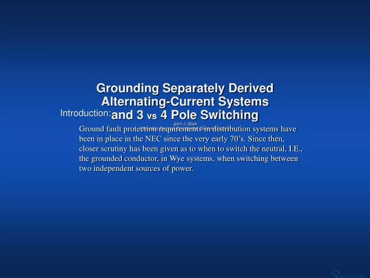
Grounding Separately Derived Alternating-Current Systems and 3 vs 4 Pole Switching John J. Stark Marketing Services Coordinator, Russelectric Inc. Introduction :.

E N D
Grounding Separately DerivedAlternating-Current Systems and 3 vs 4 Pole SwitchingJohn J. StarkMarketing Services Coordinator, Russelectric Inc. Introduction: Ground fault protection requirements in distribution systems have been in place in the NEC since the very early 70’s. Since then, closer scrutiny has been given as to when to switch the neutral, I.E., the grounded conductor, in Wye systems, when switching between two independent sources of power.
Consider the GFP problem when applying transfer switches : There are many applications where switching the neutral is the most practical of all methods. The most widely accepted method is to utilize a 4 pole transfer switch, to separate the grounds between two or more than two sources. This will satisfy code requirements and will insure that faults to ground will not have multiple paths to follow. This will allow the GFP to monitor the actual faults.
Ground Fault Protection Requirements: National Electric Code, Section 230.95: 230.95 Ground-Fault Protection of Equipment Ground-fault protection of equipment shall be provided for solidly grounded wye electric services of more than 150 volts to ground but not exceeding 600 volts phase-to-phase for each service disconnect rated 1000 amperes or more. The grounded conductor for the solidly grounded wye system shall be connected directly to ground through a grounding electrode system, as specified in 250.50, without inserting any resistor or impedance device. The rating of the service disconnect shall be considered to be the rating of the largest fuse that can be installed or the highest continuous current trip setting for' which the actual overcurrent device installed in a circuit breaker is rated or can be adjusted. The provisions of 230.95 covering the ground-fault protection of equipment were first required in the 1971Code Ground-fault protection of equipment shall be provided for solidly grounded wye electric services of more than 150 volts to ground but not exceeding 600 volts phase-to-phase for each service disconnect rated 1000 amperes or more. The grounded conductor for the solidly grounded wye system shall be connected directly to ground through a grounding electrode system, as specified in 250.50, without inserting any resistor or impedance device. The rating of the service disconnect shall be considered to be the rating of the largest fuse that can be installed or the highest continuous current trip setting for' which the actual overcurrent device installed in a circuit breaker is rated or can be adjusted. The provisions of 230.95 covering the ground-fault protection of equipment were first required in the 1971Code (pertinent verbiage)
National Electric Code, Section 230.95: In addition to the requirements of the N.E.C., Ground Fault Protection for systems which are less than 1000 amperes, using the same code section as a guide, is accepted by most engineers.
2011 National Electric Code, Section 250.30 - Grounding and Bonding Systems (We’ll use two examples at 120/208, 3 ph, 4 w): Let’s take a look at the one-lines of the neutral (grounded) conductor… Keeping in mind the distinction between the Grounding conductor (equipment grounding conductor), and the Grounded conductor (neutral conductor)… N.E.C. Exhibit 250.12 N.E.C. Exhibit 250.11 Gen Gen Notice that the Neutral conductor is solidly connected, thus, not separately derived. Notice that the Neutral conductor is switched, (break-before-make) thus, separately derived.
N.E.C. Informational Note No.1: An alternate ac power source, such as an on-site generator, is not a separately derived system if the grounded conductor is solidly interconnected to a service-supplied system grounded conductor. An example of such a situation is where alternate source transfer equipment does not include a switching action in the grounded conductor and allows it to remain solidly connected to the service-supplied grounded conductor when the alternate source is operational and supplying the load served. N.E.C. N.E.C. Exhibit 250.12 N.E.C. Exhibit 250.11 Gen Gen
Exhibits 250.11 and 250.12 depict a 208Y/120-volt, 3-phase, 4-wire electrical service supplying a service disconnecting means to a building. A feeder is installed from the service equipment to the normal power terminals of a transfer switch. The emergency or alternate power terminals of the transfer switch are supplied by a feeder that is supplied by a generator with a 208Y/120-volt, 3-phase output. Emergency, legally required standby, and/or optional standby loads are supplied from the load terminals of the transfer switch in accordance with the applicable requirements of Articles 700, 701 (Legally Required Standby Systems), and 702 (Optional Standby Systems). N.E.C. N.E.C. Exhibit 250.12 N.E.C. Exhibit 250.11 Gen Gen
Exhibit 250.11 depicts a 3 pole ATS with solid neutral. The neutral conductor from the generator to the load is not disconnected by the transfer switch. The system has a direct electrical connection between the normal grounded system conductor (neutral) and the generator neutral through the neutral bus in the transfer switch, thereby grounding the generator neutral. Because the generator is grounded by connection to the normal system ground, it is not a separately derived system and there are no requirements for grounding the neutral at the generator. The conductor installed between the equipment grounding terminal of the transfer switch and the generator frame/equipment grounding terminal is either an equipment grounding conductor or a supply side bonding jumper, depending on where the first overcurrent device in the generator feeder circuit is located. See 250.35(B) for the requirement covering generators supplying systems that are not separately derived. N.E.C. N.E.C. Exhibit 250.11 Gen
In Exhibit 250.12, the grounded conductor (neutral) is connected to the switching contacts of a 4-pole transfer switch. Therefore, the generator system does not have a direct electrical connection to the other supply system grounded conductor (neutral), and the system supplied by the generator is considered separately derived. This separately derived system (3-phase, 4-wire, wye-connected system that supplies line-to-neutral loads) is required to be grounded in accordance with 250.20(B). The methods for grounding the system are specified in 250.30(A). N.E.C. Note: The above is only true when employing open transition (break-before-make), fully rated neutral switching contacts. N.E.C. Exhibit 250.12 Gen
Section 250.30(A)(l) requires separately derived systems to have a system bonding jumper connected between the generator frame and the grounded circuit conductor (neutral). The grounding electrode conductor from the generator is required to be connected to a grounding electrode. This conductor and the grounding electrode are to be located as close to the generator as practicable, according to 250.30(A)(4). However, because the generator feeder is supplying a building that is also supplied by an ac service, 250.58 requires both supply systems to be connected to the same grounding electrode system. N.E.C. N.E.C. Exhibit 250.12 Gen
If it is determined by the engineer that a separately derived system is not required, then 3 pole transfer switches are acceptable. N.E.C. Exhibit 250.11 Gen
More on 4 Pole Switching: Construction Considerations and Precautions for Specifying and Applying 4 pole Switches: Switching the Neutral Conductor: 1. The neutral switching contacts and related arc quenching means must be identical to and mounted on the same shaft and mounting base as the associated main contacts. This will insure proper mechanical synchronism and alignment and avoid any possibility that the neutral contacts will fail to open or close when they should. This would not possible with an adjunct type neutral switching accessory, rather than a true four pole switch. 2. Being completely identical, the neutral switching contact would have the same current rating as the main contacts. It would have identical withstand ratings should a fault occur on one line, thus unbalancing the system. The neutral contacts can be stressed as much as the main contacts. Suggested Specification Insert: “On 3 phase, 4 wire systems utilizing ground fault protection, a true 4 pole switch shall be supplied with all four poles mounted on a common shaft. The continuous current rating and the closing and withstand rating of the fourth pole shall be identical to the rating of the main poles. Ancillary overlapping neutrals shall not be permitted."
Example: a 4 Pole Transfer Switchbase with Fully Rated Integral Switched Neutral Power Poles NeutralPole
CAD Rendering (side view) of a true 4 pole switch with insulating barriers omitted for clarity. Notice the neutral pole and contacts are indistinguishable from the power poles and contacts because –in fact- they are the same and they operate the same.
To meet the stringent requirement of 4-pole switching applications brought about by the widespread use of GFP (Ground Fault Protection) equipment, truly synchronous contact operation and fully rated construction as an integral design in4-pole transfer switches is completely necessary. Conclusion: To satisfy code requirements for GFP, and separately derived power systems, true 4 pole switching will insure that faults to ground will not have multiple paths to follow and will allow the GFP system to accomplish its purpose.