Download
1 / 21
210 likes | 229 Views
This document provides an overview of the physical layout and operational infrastructure components of the ATLAS High-Level Trigger (HLT) and Data Acquisition (DAQ) systems, including housing, power supply, rack configuration, cabling, and system administration.

E N D
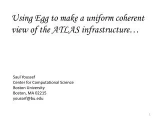
ATLAS DAQ/HLT Infrastructure H.P. Beck, M. Dobson, Y. Ermoline, D. Francis, M. Joos, B. Martin, G. Unel, F. Wickens. Acknowledgements: H. Burckhart, W. Iwanski, K. Korcyl, M. Leahu 11th Workshop on Electronics for LHC and future Experiments, 12-16 September 2005, Heidelberg, Germany
ATLAS HLT and DAQ physical layout SDX1 ROS – Read Out System SV – Supervisor DFM – Data Flow Manager USA15 • Read-Out Subsystems underground • 152 ROSes (max 12 ROLs per ROS) • HLT and EB processor farms on the surface • Rack-mounted PCs and network switches • ~2500 components in ~120 racks
HLT and DAQ operational infrastructure components • Housing of HLT/DAQ system - 2 floor counting room in SDX1 building • Metallic structure (electronics is heavy nowadays) • Lighting, ventilation, mixed water piping and cable trays • Power supply (from network and UPS) • Housing and operation of rack-mounted PCs and network switches • Rack selection and component mounting • Power distribution and heat removal • Power and network cabling • Operational infrastructure monitoring • Standard ATLAS DCS tools for rack parameter monitoring • Linux and IPMI tools for individual PC internal monitoring • Computing farm installation, operation and maintenance • Rack configuration and cabling databases • System administration
Counting room in SDX1 for DAQ/HLT system • Size of barrack constrained by crane, shaft to USA15 and existing walls of SDX • Housing 100 racks 600 mm x 1000 mm, up to 52U (height floor to ceiling ~2600 mm) • Metallic structure initially designed for 500 kg/rack, re-designed for 800 kg/rack • Air-conditioning removes ~10% of the heat dissipated, other 90% are removed via water-cooling Design Temporary power supply Construction Lighting and ventilation Cable trays Water piping
Housing of equipment “Standard” ATLAS 52U rack • Investigated 2 options • Modified “standard” 52U ATLAS rack for ROSes in USA15 • positions already defined • weight not an issue in USA15 • uniform to other racks in USA15 • Industry standard Server Rack for SDX1 (e.g. RITTAL TS8) • bayed racks with partition panes for fire protection • height and weight limits • lighter racks, more flexible mounting for PCs • Mounting of equipment • Front mounted PC’s on supplied telescopic rails • Rear/front mounted switches (on support angles if heavy) • All cabling at rear inside the rack RITTAL TS8 47/52U rack
Cooling of equipment “Standard” ATLAS 52U rack • Common horizontal air-flow cooling solution for ATLAS and RITTAL racks • Outcome of joint “LHC PC Rack Cooling Project” • Requirement: ~10 kW per rack • A water-cooled heat exchanger fixed to the rear door of the rack • CIAT cooler mounted on the rear door (+150 mm) • 1800x300x150 mm3 • Cooling capacity – 9.5 kW • Water: in 15°C, out 19.1°C • Air: in 33°C, out 21,5 °C • 3 fan rotation sensors RITTAL 47U rack Water in/out
Power Control Ventilation Auxiliary Power to equipment Powering of equipment in SDX1 (prototype rack study) • Powering problems and (as simple as possible) solutions • High inrush current – D-curve breakers and sequential powering • Harmonic content – reinforced neutral conductor with breaker • 11 kVA of apparent power delivered per rack on 3 phases, 16A each • ~10 kW of real power available (and dissipated) with typical PFC of 0.9 • 3 individually controllable breakers with D-curve for high inrush current • First level of sequencing • 3 sequential power distribution units inside the rack (e.g. SEDAMU from PGEP) • Second level of sequencing • 4 groups of 4(5) outlets, max 5A per group, power-on is separated by 200 ms • Investigated possibilities for individual power control via IPMI or Ethernet controlled power units
Switchboard Distributing cupboards Powering of equipment – proposed final implementation (1) • Transformer (in front of SDX1) to power the switchboard • Power from the switchboard delivered to 6 distributing cupboards on 2 levels • Each cupboard controls and powers 1 row of racks (up to 18 racks) • Two 3-phase cables under the false floor from the cupboard to each rack • Distribution cupboard • 400 A breaker on the input • 1 Twido PLC • Read of ON/OFF and Electrical Fault status of all breakers in the row • 16A breakers on the output • One breaker per power cable • Each breaker is individually turned ON by DCS via PLC
2 x 16A D type 3 phase breakers PLC Rack Side 2 x 3 phase manual switches Powering of equipment – proposed final implementation (2) • 3U distribution box on the bottom of each rack (front side) to provide distribution inside a rack • 2 manual 3 phase switches on the front panel to cut power on 2 power lines • Input and output cables on the rear panel • Distribution from two 3 phase power lines to 6 single phase lines • Flat cable distribution on the back side of the rack • 6 cables from the distribution box to 6 flat cables • 6-7 connectors on each flat cable Installation is designed to sustain 35 A of inrush current (peak) from 1 PC for ~35-40 PCs per rack
Monitoring of operational infrastructure • SDX1 TDAQ computing room environment monitored by: • CERN infrastructure services (electricity, C&V, safety) and • ATLAS central DCS (room temperature, etc) • Two complementary paths to monitor TDAQ rack parameters • by available standard ATLAS DCS tools (sensors, ELMB, etc.) • by PC itself (e.g. – lm_sensors) or farm management tools (e.g. – IPMI) • What is monitored by DCS inside the racks: • Air temperature – 3 sensors • Inlet water temperature – 1 sensor • Relative humidity – 1 sensor • Cooler’s fan operation – 3 sensors • What is NOT monitored by DCS inside the racks: • Status of the rear door (open/closed) • Water leak/condensation inside the cooler • Smoke detection inside the rack Quartz TF 25 NTC 10 kOhm Precon HS-2000V RH
Standard ATLAS DCS tools for sensor readout • The SCADA system (PVSS II) with OPC client / server • The PC (Local Control Station) with Kvaser PCIcan-Q (4 ports) • CAN power crate (16 branches of 32 ELMBs) and CANbus cable • The ELMB, motherboards and sensor adapters Kvaser ELMB CAN power crate Motherboard
To next rack To PSU CANbus cables Sensors location and connection to ELMB • Sensors location on the rear door of TDAQ rack • All sensor signals (Temperature, Rotation, Humidity) and power lines are routed to a connector on the rear door to simplify assembly • Flat cables connect these signals to 1 of 4 ELMB motherboard connectors • 3 connectors receive signals from 3 racks, 1 spare connector for upgrades • 1 ELMB may be used for 3 racks
Use of internal PC’s monitoring • Most PC's now come with a hardware monitoring chips (e.g. LM78) • Onboard voltages, fan status, CPU/chassis temperature, etc. • a program, running on every TDAQ PC, may use lm_sensors package to access parameters and send this information using DIM to DCS PC • IPMI (Intelligent Platform Management Interface) specification • platform management standard by Intel, Dell, HP, and NEC • a standard methodology for accessing and controlling bare-metal hardware, even without software installed or running • based on a specialized micro-controller, or Baseboard Management Controller (BMC) - it is available even if system is powered down and no OS loaded http://it-dep-fio-ds.web.cern.ch/it-dep-fio-ds/presentations.asp Supermicro IPMI Card
Preparation for equipment installation Design drawing Rack content 6 Pre-Series racks Rack numbering (Y.03-04.D1)
Computing farm – Pre-Series installation • Pre-Series components in CERN (few % of the final size) • Fully functional, small scale, version of the complete HLT/DAQ • Installed in SDX1 lower level and USA15 • Effort for physical installation • Highlight and solve procedural problems before we get involved in the much larger scale installation of the full implementation • Will grow in time – 2006: + 14 racks, 2007: + 36 racks…
Cabling of equipment • All cables are defined and labeled: • 608 individual optical fibers from ROS to Patch Panels • 12 bundles of 60 fibers from USA15 patch panels to SDX1 patch panels • Individual cables from Patch Panels to the central switches and then to PCs • Cables labeling is updated after installation • Cable installation: • tries to minimize cabling between racks, to keep cabling tidy and to conform to minimum bend radii • not using cable arms but uncable a unit before removal
Computing farm – system management • System Management • System Management of HLT/DAQ has been considered by SysAdmin Task Force, topics addressed: • Users / Authentication • Networking in general • Booting / OS / Images • Software / File Systems • Farm Monitoring • How to Switch on/off nodes • Remote Access & Reset with IPMI • IPMI daughter card for PC motherboard - experience with v1.5. which allows access via LAN; • to reset, to turn off & on; to login as from the console; to monitor all sensors (fan, temperature, voltages etc.) • Cold start procedure tested recently for Pre-Series: • IPMI used to powerdown/boot/monitor machines • scripts for IPMI operations (booting all EF nodes etc...) are being written
CPN Users access CERN IT Bypass Gateway (login necessary) CTN ATCN Central Server 1 Central Server 2 Sync path Alternative sync paths Sync paths Local Server n Local Server 1 Local Server 2 Client 1 Client 1 Client 1 Service path Client n Client n Client n Clients are netbooted. Computing farm – Point 1 system architecture CERN Public Network CERN Technical Network ATLAS Technical and Control Network
Computing farm – file servers/clients infrastructure • Gateway & Firewall services to CERN Public Network • ssh access • Tree servers/clients structure • Central File Server - 6 Local File Servers - ~70 clients • all files come from a single (later a mirrored pair) Central File Server • All clients are net-booted and configured from Local File Servers (PC’s & SBC’s) • maximum of ~30 clients per boot-server to allow scaling up to 2500 nodes • a top-down configuration (from machine specific / detector specific / function specific / node specific) provided • when modified, the atlas software is (push) synced from top down to each node with disk • software installation mechanism and responsibilities being discussed with Offline and TDAQ • Node logs are collected on the local servers for post-mortem analysis if needed
Computing farm – Nagios farm management • All farm management related functions are unified under a generic management tool Nagios (LFS and Clients): • a unique tool to view the overall status, issue commands, etc… • using IPMI where available • otherwise ssh and lm_sensors • mail notification for alarms (e,g, - temperature) • DCS tools will be integrated
Conclusions: • Good progress made in developing final infrastructure for the DAQ/HLT system • power and cooling - has become a major challenge in computer centers • installation • monitoring and farm management • Pre-series installation has provided invaluable experience to tune/correct the infrastructure, handling and operation • Making good progress towards ATLAS operation in 2007 • Looking forward to the start of physics running