Download
1 / 44
440 likes | 450 Views
This study focuses on the design and optimization of the booster and mainring lattice for the CEPC (Circular Electron Positron Collider) project. Two possible options, the normal bend scheme and the wiggling bend scheme, are investigated. The parameters and optimization results are presented.

E N D
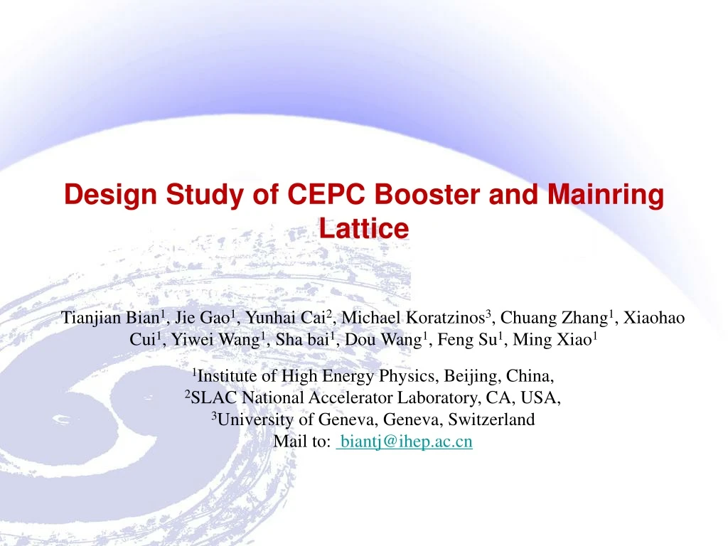
Design Study of CEPC Booster and Mainring Lattice Tianjian Bian1, Jie Gao1, Yunhai Cai2, Michael Koratzinos3, Chuang Zhang1, Xiaohao Cui1, Yiwei Wang1, Sha bai1, Dou Wang1, Feng Su1, Ming Xiao1 1Institute of High Energy Physics, Beijing, China, 2SLAC National Accelerator Laboratory, CA, USA, 3University of Geneva, Geneva, Switzerland Mail to: biantj@ihep.ac.cn
Outline • Design Goal of CEPC Booster. • Possible Options: • Normal Bend Scheme. • Wiggling Bend Scheme. • CEPC Mainring Design • Optimization Code Preparation • Moola:Modular¶llel Optics Optimization for LAttice • Summary
Injected Beam Circulating Beam p/2 Closed orbit kickers Design Goal • Consideration of injection • Inject in X direction.
Design Goal • Consideration of injection • Emit in mainring is 2E-9 m*rad, asuming beta_x=590 meter in the injection point. • Asuming DA_x=20 sigma@dp=0.5% in the mainring. • Asuming beta_x=590 meter in the injection point. • The total space for injection: • 8 sigma is retained for revolution beam to get enough quantum life time: • 6 sigma is retained for injection beam to loss less particles: • 3.2mm is lefted for septum and emit of booster@120Gev is 3.5E-9 m*rad.
Design Goal • Design Goal • For injection, emit of booster@120Gev should be about 3.5E-9 m*rad. • 1 percent energy acceptance for enough quantum lifetime. • DA_x and DA_y should bigger than 5~6 sigma for injection. • Linac parameters • From : Li Xiaoping, Pei Guoxi, etc, "Conceptual Design of CEPC Linac and Source".
Normal Bend Scheme • Introduction of Normal Bend Scheme • The inject energy is 6GeV. • The earth field is about 0.5Gs, so in the normal bend scheme start at 30Gs@6GeV may be difficult. • Shielding and correcting are needed. • With earth field, booster is a broken ring. So the first turn orbit correction is important. After the first turn orbit correction, the circular beam is existed and the closed orbit correction can be done.
Linear Optics • 90 degree FODO • FODO length:70 meter
SF1 SF1 SF2 SF2 SF3 SF3 SF4 SF4 SD1 SD1 SD2 SD2 SD3 SD3 SD4 SD4 Chromaticity Optimization • Sextupole scheme • Non-interleaved sextupoles are used. • Another pair of sextupole with the same strength apart by 90°phase advance for cancel the second order chromaticity automatically. • 8 sextupole families, optimize using both symbolic differential algebra and numeric way. • Only optimizing the 8 sextupole families is not enough. • Appropriate phase advance between arcs is necessary.
Chromaticity Optimization • Optimization result before optimization after optimization
Earth field Orbit Correction • First turn orbit correction • As we have said, the first turn orbit correction is important. It is similar to the closed orbit correction. This code is finished using Matlab.
Earth field Orbit Correction • Closed orbit correction • After the first turn orbit correction, the closed orbit is existed. Closed orbit after first turn orbit correction and closed orbit correction Closed orbit after first turn orbit correction
CEPC Booster Error Estimate From Bai Sha
DA result • Tune:190.61/190.88 and cavity on With error and orbit correction, dp=0.01 With error and orbit correction, dp=0.0
Booster Parameters • Parameter List for Normal Bend Scheme.
Booster Parameters • Parameter List for Normal Bend Scheme.
Conclusion • With error, orbit correction, cavities on and tune 0.61/0.88, DA_x=8.6sigma,DA_y=10.1sigma@dp=0% • With error, orbit correction, cavities on and tune 0.61/0.88, DA_x=6.7,DA_y=6.5@dp=1% • Contrast with the design goal we have proposed in previous section, this design is reasonable and meet requirements.
Wiggling Bend Scheme • Introduction of Wiggling Bend Scheme • The inject energy is 6GeV. • If all the dipoles have the same sign, 30Gs@6GeV may cause problem. • In wiggling bend scheme, adjoining dipoles have different sign to avoid the low field problem. • The picture below shows the FODO structure. • The wiggler scheme using the same sextupole scheme and magnet error and the wiggler scheme has little or no effect on dynamics.
Linear Optics • 90 degree FODO • FODO length:70 meter
DA result • Tune:190.61/190.88 and cavity on with error, dp=0 with error, dp=0.0 with error, dp=0.01 with error, dp=0.01
Booster Parameters • Parameter List for Alternating Magnetic Field Scheme.
Booster Parameters • Parameter List for Alternating Magnetic Field Scheme.
Conclusion • In the wiggling bend scheme, strength of dipole increase from 30Gs to -129.18/+180.84 Gs. • Shorter damping times are obtained, which is 4.7 seconds. • A ramping method of is alternating magnetic field booster proposed. • Serveal tunes has been test. Some tunes are sensitive to magnet errors, some are not. 0.61/0.88 seems good. • With error, cavities on and tune 0.61/0.88, DA_x=9.2,DA_y=9.6@dp=0% • With error, cavities on and tune 0.61/0.88, DA_x=6.6,DA_y=6.4@dp=1%
CEPC Mainring Design From:Dou
CEPC Mainring Design • CEPC Mainring Design The chromaticity formulae are derived for X direction@L=50 m, bend angle alpha=2*pi/1788 and thin lens condition
CEPC Mainring Design • CEPC Mainring Design • The inject energy is 6GeV.
CEPC Mainring Design • CEPC Mainring Design • The inject energy is 6GeV.
CEPC Mainring Design • For CEPC Mainring, large energy acceptance is needed. Even more than 2%. So chromaticity optimization is important. • Finally, we find a sextupole module with 20 sextupole families that can zero out the chromaticity order by order. 【
X=72.8sigma Y=1237.2sigma @0% X=48.6sigma Y=824.8sigma @0.5% X=24.3sigma Y=421.4sigma @1% CEPC Mainring Design • In the booster, dynamic aperture drop about 28.3% for 1% off-momentum particles. • But dynamic aperture for mainring drop about 66.7% for 1% off-momentum particles. • Why?
CEPC Mainring Design Booster V.S. Mainring
CEPC Mainring Design • CEPC Mainring Design • From dynamic apture: • From nonlinear parameter:
CEPC Mainring Design • CEPC Mainring Design • In this case, we zero out the 2nd and 3rd order chromaticity, but the 4th order is so big that limit the energy acceptance because we didn't control the 4th chromaticity in the optimization process. • So, we need to optimize the 2nd, 3rd and 4th order together to get better result. • For further study, more and more nonlinear parameters will be included. • Maybe the multi-objective optimization algorithm is a good choice. • That is also one of the motivations to develope new code.
Moola:Modular¶llel Optics Optimization for LAttice • Introduction of Moola • In the lattice design process, especially in the challenging project like CEPC, we want to control every thing(such as the twiss, high order nonlinear parameter and so on), and using them for optimization. • Lattice design code like Mad and Sad can complete some thing very well, but they don't let us do what ever we want, beacuse we can't handle the code. • Based on this requirement, we need own code. • Moola is a c++ library, which is modular¶llel. • Moola is linked to Zlib.
Moola:Modular¶llel Optics Optimization for LAttice Alignment Simulator* Element Simulator High Order Fields Error Simulator Fringing Fields Simulator* Beamline Modify Radiation Parameters* Beamline LinkList Twiss* Orbit correction* Tracker Frequency Map Analysis Dynamic Aperture Arbitrary Order One Turn Map(OTM) Optimization Algorithm Zlib Arbitrary Order Nonlinear Parameters Optimization* *in the developing process
Moola:Modular¶llel Optics Optimization for LAttice • Main physics base • Hamilton and canonical coordinates • Fourth-order symplectic integrator
Moola:Modular¶llel Optics Optimization for LAttice • CEPC mainring results from Moola
Moola:Modular¶llel Optics Optimization for LAttice • CEPC mainring results from Moola 2500 particles, 256 turns in 109 seconds
Moola:Modular¶llel Optics Optimization for LAttice • CEPC mainring results from Moola 2500 particles, 512 turns in 219 seconds
Moola:Modular¶llel Optics Optimization for LAttice • CEPC mainring results from Moola • Arbitrary order one-turn-map • Linear optics • Arbitrary order chromaticity • Detuning terms
Moola:Modular¶llel Optics Optimization for LAttice • Introduction of Moola • Moola is still preliminary, many functions is waiting to be added. • With all the nonlinear parameters in my computer memory, we can call them in any optimization algorithm(like all kinds of evolution algorithm). • In the booster further design and the mainring design, Moola will play a more important role.
Summary • In this report, we proposed a design of both normal scheme and wiggler scheme. • Normal scheme: • With error, orbit correction, cavities on and tune 0.61/0.88, DA_x=8.6sigma,DA_y=10.1sigma@dp=0% • With error, orbit correction, cavities on and tune 0.61/0.88, DA_x=6.7,DA_y=6.5@dp=1% • Wiggler scheme: • With error, cavities on and tune 0.61/0.88, DA_x=9.2,DA_y=9.6@dp=0% • With error, cavities on and tune 0.61/0.88, DA_x=6.6,DA_y=6.4@dp=1% • Contrast with the design goal we have proposed in previous section, both of the two design are reasonable and meet requirements. • For the mainring design, we have a good idea for chromaticity correction, further study is needed. • Moola, an optimization code is in developing process for further study.
Summary • Optimization of lattice: reference lattice design, Lcell=47.2m vs. Lcell=70.8 m. (ZC, CXH) • Linear optics • Chromaticity correction and dynamic aperture • Machine errors and correction • Sawtooth effect and their correction; • Low field at injection and its tolerance: test, simulation and mitigation; (BTJ) • Consideration of a pre-booster • Instability: further simulation study.(BTJ) • Injection: physical design. (ZC) • Ejection: work together with collider injection. (CXH) • Design of transfer line from linac to booster. (ZC) • Design of transfer line from booster to collider. (CXH) • Provide a full parameter list of reference design including field, aperture, RF, kicker pulse length, vacuum, diagnostics, and tolerances.
CEPC Mainring Design • Achromatic module • Sextupole pair for the 3rd order, but it can't be used in the mainring. So 2nd and 3rd order chromaticity can only cancelled by appropriate sextupole families. • Octupole pair for the 4rd order
Plan • There are 6 months left, our plan is: • Optimization code 2 month • Lattice redesign, with injection and ejection. 2 month • The process of ramping. 1 month • Design goal of CDR • For injection, emit of booster@120Gev should be about 3.5E-9 m*rad. • 1 percent energy acceptance for enough quantum lifetime. • DA_x and DA_y should bigger than 7~8 sigma for injection for both on-momentum and off-momentum.