Download
1 / 54
610 likes | 859 Views
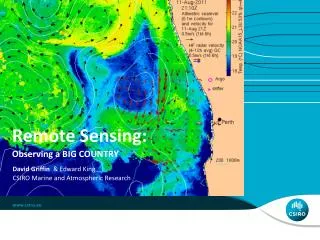
Remote Sensing & Landscape Ecology: an overview. Ranjeet John 02/11/09.

E N D
Remote Sensing & Landscape Ecology: an overview Ranjeet John 02/11/09
Remote sensing is the small or large-scale acquisition of information of an object or phenomenon, by the use of either recording or real-time sensing device(s) that is not in physical or intimate contact with the object. (from Wikipedia) the term, “remote sensing,” was first introduced in 1960 by Evelyn L. Pruitt of the U.S. Office of Naval Research. http://employees.oneonta.edu/baumanpr/geosat2/RSHistory/HistoryRSPart1.htm
Remote Sensing in the most generally accepted meaning refers to instrument-based techniques employed in the acquisition and measurement of spatially organized (most commonly, geographically distributed) data/information on some property(ies) (spectral; spatial; physical) of an array of target points (pixels) within the sensed scene that correspond to features, objects, and materials, doing this by applying one or more recording devices not in physical, intimate contact with the item(s) under surveillance (thus at a finite distance from the observed target, in which the spatial arrangement is preserved); techniques involve amassing knowledge pertinent to the sensed scene (target) by utilizing electromagnetic radiation, force fields, or acoustic energy sensed by recording cameras, radiometers and scanners, lasers, radio frequency receivers, radar systems, sonar, thermal devices, sound detectors, seismographs, magnetometers, gravimeters, scintillometers, and other instruments. NASA remote sensing tutorial (http://rst.gsfc.nasa.gov/Intro/Part2_1.html)
65 feet long … • 5 S’s of PI (shape, size, shadow, site, shade) • "If you walk in a field in the early morning, you create a path through the field when you disturb the dew. This could be seen from 100 miles up in space. We see things the groundling is not cognizant of at all on Earth." - Dino Bruggioni http://www.pbs.org/wgbh/nova/spiesfly/brugioni.html http://airphotos.nrcan.gc.ca/photos101/photos101_info_e.php
SATELLITE IMAGERY • Landscape Scale: Landsat 7/ETM+ (30m) • Regional Scale:Terra/ MODIS (1000m, 500m, and 250m) 10 / 2003
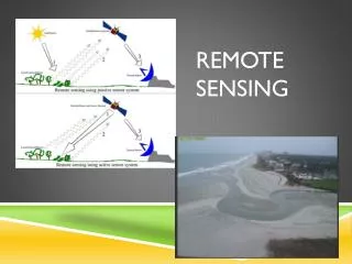
Active: energy generated from within the sensor system is beamed outward, and the fraction returned is measured e.g., radar Passive (optical): energy leading to radiation received comes from an external source, e.g., Sun from your reading, can you give me examples for the above.. Types of Remote sensing
Spatial resolution is commonly expressed as the most closely spaced line-pairs per unit distance that can be distinguished. • Spectral res. : can be defined by the limits of the continuous wavelengths (or frequencies) that can be detected in the spectrum • Radiometric res. : relates to levels of quantization that can be detected or be established to improve scene quality (for eg. tonal contrast or 256 shades of grey= 8 bit vs human eye = 16 levels) . 1 bit = 2 quantization levels • Temporal res. : refers to the length of time it takes for the satellite to complete one entire orbit cycle. However, owing to possible overlaps of adjacent swaths, the repeat cycle may change. If a satellite has a pointing capability, the temporal resolution could be higher. NASA remote sensing tutorial (http://rst.gsfc.nasa.gov/Intro/Part2_1.html)
http://www.sat.dundee.ac.uk/sensors.html http://ls7pm3.gsfc.nasa.gov/Images/etmpics/bands.gif http://earthobservatory.nasa.gov/Features/LandCover/land_cover_2.php
Portions of the EM spectrum that can pass through the atmosphere with little or no attenuation are referred to as atmospheric windows The figure shows areas of the spectrum that can pass through the atmosphere without attenuation (peaks) and areas that are attenuated (valleys) Atmospheric windows http://www.geo.unizh.ch/~kaeaeb/glims/glims.html
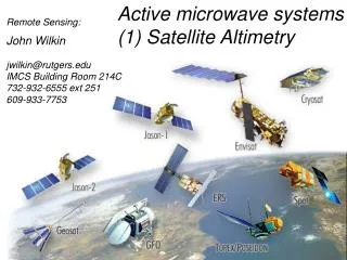
Terra Orbit Polar sun synchronous orbit http://modis.gsfc.nasa.gov/gallery/#
http://landsathandbook.gsfc.nasa.gov/handbook/handbook_htmls/chapter1/chapter1.htmlhttp://landsathandbook.gsfc.nasa.gov/handbook/handbook_htmls/chapter1/chapter1.html
Dichroic lens/prism Sensor motion Sensor motion TM/Landsat, MODIS/Terra SPOT (France), IRS (India) Across track or whiskbroom Along track or whiskbroom From Jensen, J. (2000) Remote sensing: and Earth resource perspective, p. 184 From: http://ceos.cnes.fr:8100/cdrom/ceos1/irsd/pages/datacq4.htm & J. Jensen (2000)
Path 126 125 124 35 Study area 2007/05/19 36 2007/09/22 2007/08/20 37 Row 2007/09/15
MODIS 1km (LST, LAI/FPAR, GPP/NPP) MODIS 500m water stress (NDSVI, LSWI) MODIS 250m EVI L7, 60m L7,30
Image processing (work flow) • Radiometric correction - atmospheric correction • Geometric correction - rectification & georeferencing • Display & Enhancement - Contrast stretching • Information extraction – image classification (supervised/unsupervised) data mining, feature extraction, spectral vegetation indices (SVIs) • Analysis outside RS/GIS, data staged in text files/excel from imagery and analyzed in statistics package
Radiometric correction • Raw DN: Digital number (0-255), for 8 bit • Radiance: is the sun’s energy reflected by a target, measured in optical units of radiance (watts/m2) radiance = slope * (DN) + intercept irradiance: sun’s energy incident on target • Reflectance: is defined as the ratio of the radiance to irradiance defines the true reflectance of the target reflectance = radiance / irradiance computed as % reflectance http://www.yale.edu/ceo/Documentation/ComputingReflectanceFromDN.pdf
the dominant atmospheric effect on remote sensing is “path radiance”; the scattering of radiation from the sun’s beam into the direction of the satellite by air molecules or by suspended particles. Some Atm. Correction methods 5s, 6s, Atcorr. MODTRAN 4 or the simple Dark object subtraction, or Psuedo-invariant object correction (subtract and normalize near black bodies & white body object pixels in the image) http://cwcaribbean.aoml.noaa.gov/bilko/module7/lesson3/images/Image12.gif
R R b a target target R d target R c target • target reflectance is a f ( ) of • Atmospheric irradiance (path radiance: Ra) • Reflectance beyond target scattered into path (Ra) • Diffuse atmospheric irradiance (scattered on target: Rc) • Multiple-scattered surface-atmosphere interaction (Rd) From: http://www.geog.ucl.ac.uk/~mdisney/phd.bak/final_version/final_pdf/chapter2a.pdf
Radiance, L Offset assumed to be atmospheric path radiance (plus dark current signal) Regression line L = G*DN + O (+) DN Target DN values Simple atm. Corr. • empirical line correction (ELC) method • targets of “known”, low and high reflectance targets in one channel are chosen e.g. non-turbid water & desert (white sands), or dense dark vegetation & snow • Assuming linear detector response, radiance, L = gain * DN + offset • e.g. L = DN(Lmax - Lmin)/255 + Lmin Lmax Lmin www2.geog.ucl.ac.uk/~mdisney/teaching/PPRS/PPRS_5/principles5.ppt
Geometric correction • Registration: is the process of making an image conform to another image (or map). • Rectification/Georeferencing: The process of assigning map coordinates to image data. • Geocoding: A special case of rectification that includes scaling to a uniform, standard pixel and to a particular map projection. • Orthorectification: a form of rectification that corrects for terrain displacement using DEMs.
3,2,1 true color https://zulu.ssc.nasa.gov/mrsid/tutorial/Landsat%20Tutorial-V1.html
4,3,2 false color https://zulu.ssc.nasa.gov/mrsid/tutorial/Landsat%20Tutorial-V1.html
5,4,2 false color https://zulu.ssc.nasa.gov/mrsid/tutorial/Landsat%20Tutorial-V1.html
NDVI = (NIR — VIS)/(NIR + VIS) http://earthobservatory.nasa.gov/Library/MeasuringVegetation/
http://www2.geog.ucl.ac.uk/~plewis/geog2021/classificationPractical/http://www2.geog.ucl.ac.uk/~plewis/geog2021/classificationPractical/
Image classification • Land cover is not the same Land use • what’s there: Land cover • How is the land being used: Land use • i.e. Anthropogenic modification of natural cover • Eg. • grass is land cover; pasture and recreational parks are land uses of grass
Supervised Classification: : requires the RS analyst to select training areas where she/he knows what is on the ground and inputs these signature/training pixels to obtain a classified image using one of these three classifiers • Parallelpiped • Minimum distance to mean • Maximum likelihood
Unsupervised Classification • Rather than defining training sets, we do not define any classes beforehand (thus avoiding user bias). • Instead, the software uses statistical approaches (below) to divide the n-dimensional space into clusters with the best separation • Iterative Self-Organizing Data Analysis (Isodata) Technique • we then assign class names to the clusters
Image Processing Flow Chart Radiometric correction MODTRAN 4 Raw DN Radiance Reflectance (TOA) Reflectance (Surface) Geometric correction Rectified image Recoded to Anderson’s Level I Unsupervised Classification
Image Processing Flow Chart (for ETM+) Radiometric correction MODTRAN 4 Raw DN Radiance Reflectance (TOA) Reflectance (Surface) Geometric correction Rectified image NDVI Fract cover (green)
http://www.umass.edu/landeco/research/fragstats/fragstats.htmlhttp://www.umass.edu/landeco/research/fragstats/fragstats.html
Land Cover/Use change in Oak Opening and Maumee state forests (1992-2001)