Download

1 / 52
520 likes | 538 Views
This project focuses on calibrating and testing fuel nozzles for gas turbine engines using specialized equipment. The system addresses issues like offensive odors and fluid loss. It includes components like the Nozzle Fixture, Airlock, Gloves, and Containment Chamber.

E N D
AAT Injector Nozzle Test Chamber P15681 Calibration Fluid Exhaust System P15681
Team Roles P15681
Agenda P15681
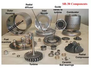
Background - AAT Advanced Atomization Technologies (AAT) • Joint venture between General Electric Aviation and Parker Aerospace • Specializes in manufacturing and testing fuel nozzles for gas turbine engines P15681
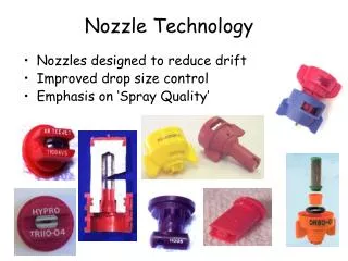
Background - Project Fuel Injection Nozzle Testing System • Qualifying fuel injection nozzles • Specialized calibration equipment • Expensive, odorous calibration fluid Problems with system • Offensive odor permeates entire building • Loss of expensive calibration fluid P15681
Problem Definition • All commercial aircraft nozzles must undergo a flow test to assure that requirements are met for spray angle. • This test uses Stoddart Solvent (MIL-PRF-7024F Type II) • Petroleum derived, clear, transparent liquid. • The fluid is very expensive and has an offensive odor • The current exhaust system is ineffective at both containing containing the odor and recovering the atomized fluid for reuse. P15681
Customer Requirements P15681
Engineering Requirements P15681
Requirements Flow Down P15681
Chamber Design • Components: • Nozzle Fixture (Integration of both tests in one location, constrain and attach nozzle) • Airlock (Test location, isolation, purge) • Gloves (Correct Material, ergonomics, attachment) • Containment Chamber (Collection and containment of liquid calibration fluid) P15681
Full Chamber P15681
Ergonomic Analysis To accommodate all operators and be safe to operate from the top and in the gloves the chamber requires 16” of travel 62” 46” P15681
Lift Table P15681
Nozzle fixture • Overview: • Combines flow and angle testing in one location • Incorporates both nozzle block-offs for flow testing and measurement system for angle testing • Roles in Engineering Requirements: • - S4: “Elapsed Time”: does not add significant cycle time P15681
Upper Door • Overview: • Provides access to the nozzle fixture inside of the airlock • O-Ring sealed, solenoid locked (to be integrated into controls system) • Roles in Engineering Requirements: • S1: “Air Quality”: Contains Calibration Fluid • S2: “Air Particle Removal”: Provides Seal for Vacuum • S8: “Calibration Fluid Leak”: Contains Calibration Fluid • S9: “Door Sealed During Operation” • S11: “Accessibility”: Easy Access for operator to Test Block P15681
Chamber Animation P15681
Gloves • Overview: • ‘Blast Chamber’ Style gloves • Allow operator access without exposure to fluid • Roles in Engineering Requirements: • S1: “Air Quality”: Fluid does not leave chamber during operator interaction • S8: “Calibration Fluid Leak”: Calibration Fluid does not escape during operator interaction • S11: “Accessibility”: Easy Access for operator to Dual Block-off P15681
Glove Testing • Gloves were tested with different sizes of people, ranging from 4ft 11in to 6ft 2in. • The placement of the gloves was comfortable for everyone to use. • The dexterity of people with smaller hands was less than ideal. Different sized gloves will need to be available for different operators. • The use of the chamber gloves is integral to the design of the system. • Use of gloves must be comfortable and easy to use. • Seal of the gloves must be maintained for system to operate properly. P15681
Mid Chamber Valves • Overview: • Ball valve interface between top and bottom chamber • Allows for separation of Air Lock from collected calibration fluid and smaller evacuation chamber • Roles in Engineering Requirements: • S1: “Air Quality”: Liquid Cal fluid is isolated to completely closed portion of chamber • S3: “Liquid Drain Rate”: Easy Access for operator to Dual Block-off P15681
Measurement • Individual motorized control of probes • Precision probe control to 0.5 thousandths of an inch* • Cameras provide easy view • LEDs increase visibility *For details on the measurement analysis reference Systems Level Design Documents on EDGE P15681
Measurement • Cameras provide excellent visibility of spray and probes • Visibility with camera of drops through mist confirmed by testing* • Visibility with camera through LED glare confirmed by testing* *For details on the measurement tests reference Systems Level Design Documents on EDGE P15681
Measurement • Cameras capture ideal vantage point for angle test • Live video displayed above probe controls • Logitech C310 HD Webcam • 720p HD Video • Easy interface with Windows • 5 MP Photos P15681
Eyedropper Test LED Interference Test at 110o LED Interference Test at 180o Mist Interference Test P15681
Drop Test Results SME – Rachel Silvastrini P15681
Mist Interference Test • Materials: • 12 Volt Car Battery • Jumper Cables • GE90 Nozzle • Water • Camera • Laptop • Dropper Results: Mist interference with the camera visibility is minimal to the point of unnoticeable. P15681
Fluids Subsystem • Mist evacuation is needed to maintain visibility during test. • The amount of air pulled from the system must be adjustable . • Evacuating mist cannot influence the testing procedure. • A two speed system combines low speed for visibility during test with high speed for fast mist evacuation at the end of the test. P15681
Subsystem Flow • By keeping the entire system sealed, no calibration fluid is allowed to escape. • All aspects of the system are sealed including chamber doors, chamber drain, drain tank, mist collector system and mist collector drain. • The test chamber will be automatically purged before allowing the chamber doors to be opened, eliminating the chance for an operator to come in contact with the atomized while also not allowing the atomized fluid to escape. • Fluid that is pulled through the mist collector is returned to the drain tank. • System is automated to reduce operator error. P15681
Fluids Subsystem - Heart • The heart of the subsystem is the AER Control System CM300. • This unit is able to pull 300 cfm from the test chamber to quickly purge the system, while being throttled back during testing in order to not effect test results. • Custom built unit will feature aluminum rotating drum to eliminate spark risk. • Unit will be fitted with an activated carbon after filter to reduce any remaining odor. • Filter can be replaced with ordinary activated carbon which is inexpensive and easily procured. • Fluid removed via the collector will be returned to the drain tank. P15681
Pump Integration • The CM300 mist collector pulls 300cfm and features a spark free aluminum rotating drum • Equipped with an automated ball valve • Corrosion resistant PVC and stainless steel fittings at all connections • A relief valve to the chamber is regulated by the control system. P15681
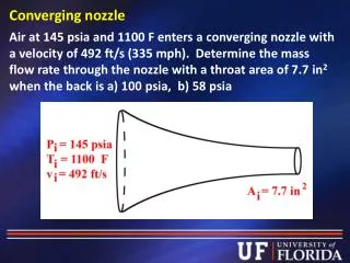
Spray Angle Testing • Engineering requirement S10 states that the test system cannot influence the test results. • Test designed to mitigate risk of the system influencing test results (spray angle). • Miniature test chamber built with ability to alter test chamber pressure as well as spray fluid through GE90 nozzle. • Test chamber was tested at atmospheric and negative pressures. • Result of test at atmospheric pressure can be seen at the left and demonstrates the control. P15681
Spray Angle Testing • Result of test at 0.5 atmosphere can be seen at the left and demonstrates the spray angle while under vacuum. • Results show that testing under a mild vacuum greatly alters test results. • Testing needs to be done at near atmospheric pressure levels in order to not influence test results. P15681
Odor Testing • A carbon/charcoal filter was then fitted to the air exit. • The fan was run and the escaping air was again tested for odor. • Cal fluid odor was greatly reduced with the addition of the filter. • An activated carbon filter will serve as the last line of defense to keep any odors from escaping the test chamber. • The experimental chamber was setup with cal fluid and a small fan to mimic odor escaping. • The escaping air was then tested for odor and recorded. P15681
Controls • Doors lock during testing • Two solenoids lock outside chamber door • Automated ball valves between upper and lower chambers • Prevents odor-filled air from leaving chamber P15681
Logic flow P15681
Wiring diagram P15681
Controls • Precision variable-speed probe control • Precision of 0.0005” • Minimum speed of 0.001 in/sec • Maximum speed of 0.5 in/sec *For details on the measurement analysis reference Systems Level Design Documents on EDGE P15681
Cycle Time • Cycle time analysis • Cycle time reduced by 2.5 minutes from current • New cycle time of ~9.3 minutes • Major time savings: No nozzle movements due to one test location, fewer X opening door, improved view and control for angle test • Time additions: putting on and removing gloves, raising and lowering table P15681
Project Schedule P15681
Risk Assessment P15681
Remaining Risks P15681
MSD II Risk Assessment P15681
Bill of Materials Subsystem: Chamber $1,909.06 Measurement $347.68 Fluid Control $5,747.85 Controls/Integration $370.26 Total $8,374.85 P15681
Action Items • Final Design Approval • Submit Purchase Orders • AER Pump • Aluminum stock / Lexan stock • Electrical Components • Hardware • Begin Manufacturing P15681
Personal Learnings • Put hard due dates on items and stick to them. • If you need help, ask for it rather than letting the problem fester. • Doing some work every day is easier than doing a lot of work over 1 or 2 days. • Performing small, inexpensive tests can go a long way into providing a proof of concept. P15681
Peer Reviews • Peer reviews were held every 3 weeks in an open forum format. • Each team member commented on every other team member in a constructive way. • Feedback given helped each team member improve as the project progressed. • A final review with our guide will take place on 12/11/14 P15681
Appendix P15681
Ergonomic Analysis System must accommodate operator heights from 62” – 76” Shoulder width range: 16.1” – 17.7” •Center to center glove separation 14” Range of distance from shoulder to ground: 50.7” – 62.17” •Chamber will require 1 foot of adjustable vertical travel *For details on the anthropometric analysis reference System Level Design Documents on EDGE P15681
Full Project Schedule P15681