Download
1 / 65
651 likes | 790 Views
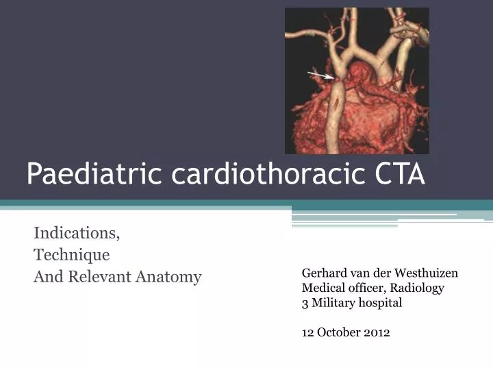
Paediatric cardiothoracic CTA. Indications, Technique And Relevant Anatomy. Gerhard van der Westhuizen Medical officer, Radiology 3 Military hospital 12 October 2012. Introduction. MDCT has revolutionised angiographic evaluation of the heart and thoracic vessels. Faster scan times

E N D
Paediatric cardiothoracic CTA Indications, Technique And Relevant Anatomy Gerhard van derWesthuizen Medical officer, Radiology 3 Military hospital 12 October 2012
Introduction • MDCT has revolutionised angiographic evaluation of the heart and thoracic vessels. • Faster scan times • Increased anatomical coverage • High quality reconstructions • Previous scanning issues in children included: • Breath-holding ability (motion artifacts) • Slow scan times causing difficulties in administation of contrast • Small gauge IV catheters • Difficult sites • Manual administration • Short distances between central line and heart.
Comparison of thoracic imaging techniques • Echocadiography • CTA more global assessment of cardiovascular structures (pulmonary arteries, anterior mediastinum, thoracic aorta etc). • CTA also includes airway and lung parenchyma. • Sedation needed with echocardiography, not always needed with CTA. • CTA is quicker, less operator dependent. • Costs the same. • CTA limited functional information, less portable, poorer temporal resolution and RADIATION . • IV access not required with echo.
Comparison of thoracic imaging techniques • MR angiography • Less need for sedation with CTA. • CTA is quicker. • Thermal stability (esp. Neonates – out of incubator). • CTA can be performed immediately post-op, no metal issues. • No radiation with MRI.
Comparison of thoracic imaging techniques • Heart catheterisation • Better physiologic and functional information. • Only intracardiac and intravacular anatomical detail. • Biplane compared to 3D options with CTA. • Radiation dose usually higher with catheterisation. • Sedation needed. • More expensive than CTA. • Technically more difficult.
Dose comparison • Study compared conventional chest CT, CTA, Gated CTA and conventional angiography: (Frush, Yoshizumi; 2006) • Average dose in children: • Conventional chest CT 1.0 to 4.0 mSv • CTA 1.0 to 4.0 mSv • Gated CTA 7.0 to 25 mSv • Conventional angiography 5.0 to 20 mSv
Indications • Detection of disease or pathology • i.e. Diagnosis • Improve clinical decision making • Need for other diagnostic testing • Use of specific intervention • No role in defining normal anatomy • No role in assessing function • Not a screening tool • Specific disease states • Extracardiac great vessel anomalies • Intracardiac shunt lesions • Post-operative anatomy • Most often used for congenital heart lesions • Trauma
CTA technique • Preperation • Ask clinician to list specific questions to adress • ? Vascular anomalies • ? Major airways, lung aeration • ? Mediastinal abnormalities – Collections, infection etc. • ? Status of upper abdomen – situs abnormalities/ abscence of spleen • Less frequent ‘protocol’ scanning than in adults
CTA technique • Example: Scan onset differs for conditions like caval-to-pulmonary artery connection compared to systemic arterial-to-pulmonary artery connection. • Artifacts: Coils, stents, clips, valves, septaloccluders, pacing wires etc. Know about them before the scan!
CTA technique • Preperation • Sedation • Mostly needed for 1-2 year age group • Can be performed by other health care providers • If child is intubated – as quickly as possible during inspiration • Quiet breathing also acceptable
CTA technique • IV access – Type • 20 or 22 gauge peripheral • 24 gauge can also provide adequate information • Long extension tubing – small contrast volume may remain in ‘dead space’ if not flushed. • Contrast volume may be less than 5 ml and 1-2 ml in ‘dead space’ is significant.
CTA technique • IV access – Location • Distance from heart – peripheral line in infant same distance as central line in adults. • Anterior mediastinum – use right arm or lower extremity (less streak artifact from left brachiocephalicvein). • Difference in evaluating IVC inflow for Fontan procedure (use lower limb or delayed scan) to evaluating pulmonary stenosis.
CTA tecnique • Avoid artifacts • Remove leads and wires from chest surface • Careful not to have watches/jewelry in gantry when injecting manually.
CTA technique • IV contrast • Type • Volume • Rate • Route • Method • Onset of scanning
CTA technique • Type • Low or isosmolar • 300mg I/ml concentration • 370mg I/ml if total volume is an issue (rarely) • Volume • MDCT lower dose • 1.5ml/kg • Max of 3 ml/kg • (Cardiac catheterisation uses 5-6ml/kg) • These doses are beneficial if repeat scanning is needed
CTA technique • Rate
CTA technique • Route • Peripheral or central • With central – opacification of pulmonary arteries almost instantaneous. • NB to know where tip of catheter is. • Hardware delays may lead to missing peak opacification with small contrast volumes. • Method • Contrast pump whenever possible • Not with 24-G, positional lines, poor backflow or lines on distal forearm, hands or feet. • Manual • Unpredictable enhancement, average rate of 1.5 ml/sec • Extravation detectors not used due to low amount of contrast used.
CTA technique • Onset of scanning • MDCT has obviated much of the calculation required • Possible to scan too early or too late • Too early – Rapid scanning time • Too late – Small volume of contrast, high cardiac output (shot period of optimal enhancement) • Three techniques: • 1. Empiric delay • 2. Bolus tracking • 3. Test bolus
CTA technique • 1. Empiric delay • Paeds: 10-20 sec • Neonates: 4-10 sec • 2. Bolus tracking • “Smartprep” • Serial enhancement at a preselected level • 10 mA (minimum tube mA) • At level of vessel/structure most critical for evaluation • Mostly at mid-ventricular level • Difference of 5-7 sec between actual enhancement and when scanning begins (software and hardware delays) • Counteract this by: • Monitor interval of 1.0 sec • Inject only after first monitoring image shows
CTA technique • 2. Bolus tracking (cont.) • Steps: • 1. Start bolus tracking display of monitoring images • 2. Start contrast injection after 1st monitoring image appears • 3. Start diagnostic scanning when opacification of desired structures begins or just prior to (more guesswork required) • 4. Stop contrast injection if scanning is complete before entire volume is given
CTA technique • 3. Test bolus • Small volume (0.5 – 1.0ml) given • Time from injection to opacification of desired structure then use with diagnostic scan with full contrast bolus. • Onset of scanning is a critical step in CTA! • With evaluation of pulmonary arteries start scanning when right ventricle starts opacifying. • Start scanning when left ventricle starts opacifying for evaluation of aorta.
CTA technique • Scan parameters: • Scan FOV • Use large FOV if child may move • Number of detector rows • Use highest available - 64 • Detector thickness • Thinnest width – 0.625mm • NB for multiplanar recons and 3D volume rendering • Tube current • According to patient’s size • kVp • Reduced for small children (80kVp under 2 years, 100 kVp up to 6 years) • Scan thickness • Include all structures of interest • Reconstruction algorithms • Volume rendering and MIP projections usually sufficient when necessary
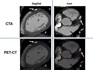
Coronary artery CT angiography • For adequate visualisation: Use isotropic in-plane and through-plane spatial resolutions <1mm (Equal voxel dimensions in x, y and z axes) • Submillimeter collimation • Pitch <1 (0.2 to 0.3) • Higher milliamperage and kVp necessary to counter increased noise. • Bolus tracking/ test bolus used. • ECG gating necessary for motionless images. • Usually retrospective ECG gating – use diastole. • Increased exposure! • Online dose modulation programs – high mA only during diastole.
Coronary artery CTA Left Right
Normal anatomy • Thoracic aorta • Pulmonary arteries • Pulmonary veins • Superior vena cava • Azygous system
Thoracic aorta • Five segments: • Aortic root • From base of heart • Includes aortic valve • Annulus • Sinus of Valsalva • Ascending aorta • From aortic root to right innominate artery • Proximal aortic arch • Right innominate artery to left subclavian artery • Distal aortic arch/isthmus • Left subclavian artery to ligamentumarteriosum • Descending aorta • Level of ligamentumarteriosum to hiatus in diaphragm
Thoracic aorta • Normal branching pattern: • Brachiocephalic trunk–R subclavian artery, R CCA • Left CCA • L subclavian artery
Pulmonary arteries • Main pulmonary artery/pulmonary trunk lies within the pericardium • Devides into larger right and smaller left pulmonary arteries • Right passes posterior to AA, SVC, R upper lobe pulmonary vein • Then devides into 2 branches – upper lobe branch and interlobar artery supplies middle and lower lobe • The left is shorter and smaller • Courses anterior to the descending aorta and left main bronchus and divides into upper and lower lobe branches.
Pulmonary veins • Typically 4 pulmonary veins: • Right and left superior and inferior • R superior – Blood from R upper and middle lobes • R inferior – Blood from R lower lobe • L superior – Blood from L upper lobe + lingula • L inferior – Blood from L lower lobe
Pulmonary veins • Variations: • Conjoined – Sup and inf open into L atrium via common ostium. More common on the left. • Accessory – Extra veins seperate from pulm veins. Occurs more commonly on the right.
SVC and azygous system • SVC formed by L and R brachiocephalic veins • Blood from upper extremities, head and neck. • Drains into R atrium • Azygous vein formed by ascending lumbar and right subcostal veins. • Blood from posterior chest and abdominal walls • Arches over right hilum and drains into posterior part of SVC. • Hemiazygous and accessory hemiazygous veins drain from the left into the azygous vein.
Normal anatomy of the heart • Cardiac chambers • Right atrium • Larger posterior atrium proper and smaller anterior atrial appendage. Devided by cristaterminalis. • Receives SVC and IVC. • Left atrium • Forms base of the heart. • Valveless R and L pulmonary veins drain into L atrium • Left auricle forms superior part of left border of heart. Seperated by interatrial septum containing fossaovale
Normal anatomy of the heart • Cardiac chambers • Right ventricle • Forms largest part of anterior surface of the heart • Contains coarse trabeculae and tapers into conusarteriosus which leads to pulmonary trunk. • Contains commonly identified muscle band- Moderator band • Left ventricle • Forms apex of the heart and left border. • Fine trabeculae, walls 3 x thicker than right. • Two prominent papillary muscles Seperated by interventricular septum – membranous and muscular parts.
Normal anatomy of the heart • Cardiac valves • Aortic valve: Right, left and non-coronary cusps • Pulmonary valve: Anterior, right and left cusps • Mitral: Aortic (anterior) and mural (posterior) leaflets • Tricuspid: Septal, anterior and posterior leaflets
Normal anatomy of the heart • Cardiac valves
Normal anatomy of the heart • Coronary arteries • Left coronary artery • From left coronary sinus • Bifurcates into LAD ad left circumflex branches • LAD gives rise to diagonal branches. • Circumflex gives rise to left marginal artery. • Right coronary artery • From right coronary sinus • Branches include: Sinuatrial nodal, AV nodal, right marginal and most commonly posterior IV branch.
Normal anatomy of the heart • Cardiac veins • Great cardiac vein accompanies LAD • Middle cardiac vein accompanies posterior IV branch • Small cardiac vein accompanies right marginal branch of RCA. • All larger branches drains into coronary sinus and into right atrium • Small anterior cardiac veins drain directly into right atrium
Thoracic vascular anomalies • Aortic anomalies: • 0.5 to 3% of population • Five groups: • Left aortic arch • Right aortic arch • Double aortic arch • Cervical arch • Innominate artery
Left arch with abberant right subclavian artery • R subclavian artery is seen on CT as last of major arterires from aortic arch. • Most common anomaly of aortic arch • 0.5 to 2% of population
Right aortic arch with aberrant left subclavian artery (Posterior view)
Double aortic arch • Two arches from single ascending aorta • Gives off own CCA and subclavian arteries • Some patients may have persistent airway obstruction related to tracheomalacia from external airway compression
Cervical aortic arch • Rare • High-riding ascending aorta above level of clavicles making a sharp downward turn.