Download
1 / 1
10 likes | 132 Views
Use the ABI cloud phase output to identify non-ice cloud pixels. Determine the fog probability for each pixel using pre-determined LUTs. Group pixels into cloud objects.

E N D
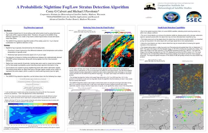
Use the ABI cloud phase output to identify non-ice cloud pixels Determine the fog probability for each pixel using pre-determined LUTs Group pixels into cloud objects Eliminate artifacts by removing any cloud objects consisting of 3 pixels or less and check spectral and spatial object metrics A Probabilistic Nighttime Fog/Low Stratus Detection Algorithm Corey G Calvert and Michael J Pavolonis* Cooperative Institute for Meteorological Satellite Studies, Madison, Wisconsin *NOAA/NESDIS/Center for Satellite Applications and Research Advanced Satellite Product Branch, Madison Wisconsin Fog Detection Approach Reducing Noise from the Final Product Small-Scale Detection Capabilities The Basics • The aviation-based level of cloud ceiling under which pilots must fly using instrument flight rules (IFR) is approximately 300m. Therefore, the goal for the GOES-R fog detection algorithm is to create a fog mask to detect liquid stratus clouds with bases lower than 300m. • The GOES-R fog detection algorithm builds off the widely-used 3.9, 11m channel combination for nighttime detection of fog. Strategy • Nighttime fog is typically characterized by the following traits: • Cloud top is close to ground so the difference between cloud temperature and surface temperature is typically small • Relatively high spectral emissivity signal (3.9,11m) at night • Fog detection is based on finding small differences between the radiometrically-derived and NWP surface temperature along with strong signals from the 3.9m pseudo-emissivity. • Rather than using specific thresholds, training data were used to create look-up tables (LUTs) that assign a probability a pixel returning certain spectral information is fog. • Cloud objects are created to group neighboring pixels with similar radiometric signals. This allows pixels within an object that have a stronger signal (usually at the center) to represent the entire object, which is useful for small-scale fog events (see far right). Algorithm • The GOES-R fog detection algorithm can be broken down into the following four steps: • Due to the spatial resolution (4km) of current GOES satellites, detecting small-scale fog events (e.g., within river valleys) is difficult. • The use of cloud objects can enhance the detection ability by allowing pixels with a stronger radiometric signal to represent pixels within the object that may not have otherwise been classified as fog. • This helps areas such as fog edges where the signal may not be strong enough by itself to be classified as fog, but has pixels in the same object with a stronger signal that is more representative. • Using the cloud objects can help to restore detail that may be missed without increasing the spatial resolution of the instrument. • The images below depict a valley fog event over Pennsylvania and upstate New York on September 17, 2007. The upper left image is the first daylight image (11:45 UTC) showing the fog within the valleys. The upper right image is the high resolution (1 km) MODIS fog/stratus product at 7:38 UTC. The lower left image is the heritage fog algorithm at 7:45 UTC displaying fog where the BTD is below -2 K. The lower right image is the corresponding GOES-R fog product creating cloud objects using the 3.9m pseudo-emissivity. The improved spatial resolution of the GOES-R ABI will greatly enhance the future GOES fog product. MODIS Fog/Stratus Product • In the upper left false color image, the white/red crosses represent surface observations meeting the no fog/fog criteria, respectively, for non ice clouds (given by GOES-R cloud type product). The light blue/magenta crosses represent surface observations meeting the same criteria respectively under multi-layer or ice clouds (areas excluded from the GOES-R fog detection algorithm). The upper right image is the GOES-R cloud type product. • The heritage fog algorithm (bottom left image) flags pixels with a 3.9-11m BTD less than -2 K. In the presence of convective clouds and non-fog water clouds this algorithm has the tendency to return ‘noisy’ pixels that are usually false alarms. • The GOES-R algorithm (bottom right image) screens these areas out using the cloud type information along with 3.9 m pseudo-emissivity data. It also uses cloud objects to group neighboring pixels with similar radiometric signals. Using a minimum object size of 3 pixels, it can significantly reduce noise in the final product. • Look-up tables were created using surface temperature bias along with the 3.9m pseudo-emissivity as predictors. “Truth” was gleaned from surface observations. • The 3.9 mclear-sky surface emissivity was also used to separate pixels with different surface types (e.g., desert and forest) which might lead to unrepresentative fog probability calculations. • Below is the fog LUT for the 3.9m pseudo-emissivity and surface temperature biasfor pixels with a clear-sky surface emissivity between 0.90 and 0.95. • Pixels with small surface temperature biases and low 3.9 m pseudo-emissivity will be given a higher probability of containing fog. For further information contact the author at corey.calvert@ssec.wisc.edu