Download
1 / 37
370 likes | 502 Views
Gamma Ray Beam Monitor Studies. Tamara Starke CUPC 2001. Introduction. Overview of HIGS Motivation Factors to Consider Procedure / Technique Observations Analysis Results & Conclusions. HIGS at FELL.

E N D
Gamma Ray BeamMonitor Studies Tamara Starke CUPC 2001
Introduction • Overview of HIGS • Motivation • Factors to Consider • Procedure / Technique • Observations • Analysis • Results & Conclusions
HIGS at FELL • Electrons are first accelerated and then injected into the electron storage ring in two “bunches”
HIGS at FELL • Electrons pass through the “wigglers,” which cause them to radiate infrared photons
HIGS at FELL • The photons are reflected by a mirror and collide with the second bunch of electrons • These photons Compton scatter with the incoming electrons, giving them very large energies (at present, 2 - 15 MeV)
HIGS at FELL • The gamma-ray photons are directed towards the experimental vault, where they can be used for physics experiments
HIGS at FELL • Gamma ray beam is collimated before entering the experimental vault
HIGS at FELL • Many different experiments can be done using these photons • For example, deuteron disintegration in heavy water
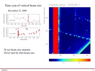
Motivation • Need to determine size and “shape” of the gamma ray beam • Beam monitor is to be used in the collimator hut at HIGS
Why is this monitor important? • Need to center the beam on a target • Ensure the beam is not drifting over time • Help identify any irregularities in the beam
Proposal • “L”-shaped detector which would scan the beam at a 45o angle to the horizontal • As it scans the beam, it will find the flux first along one dimension, clear the beam spot, and then along the other • Detector made of plastic scintillator
Goals of the Study • Need to determine the optimal dimensions of the monitor and determine whether a converter or absorber was required • See how different factors affect the monitor’s performance
Factors to Consider • Detectors of different widths, thicknesses, and arm lengths • Gamma ray beam of different fluxes • Gamma ray beam of different energies • Other elements in the beam’s path • Effects of a converter or absorber
Factors to Consider • Maximum detection rates allowable • Minimum total counts required • Scan time required • Resolution of the beam scan • Accuracy of the monitor
GEANT simulation software • GEANT is software produced by CERN • Simulates experiments based on what the user enters into the code
Examples • Simple or complex geometries
Examples • Different beam spots
Examples • Any code to reproduce the role of instruments such as PMTs and the associated electronics
Procedure • Ran many different simulations using GEANT, changing only one thing at a time • For example, the detector thickness was changed or different beam elements were added
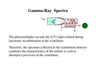
Data Acquisition • Any particles which deposited energy in the scintillator material in each of its positions were counted and plotted • These plots were compared with the plots of original beam intensity using the 2 test • Kept text and postscript files of the results of the scan
Observations • The simulations produced a large amount of data which could be used to determine the effects of certain changes
Observations • Effects of changing the detector thickness • Thicker monitors provided a greater probability of interaction for the photons, so the number of photons which deposited energy in the monitor increased with the monitor thickness
Observations • Effects of changing the detector width • Wider monitors did slightly increase the amount of energy deposited into the monitor, but caused a decrease in the resolution of the monitor
Observations • Effects of changing the detector arm length • A greater arm length allowed for a greater measure of the “background” to be determined
Observations • Gamma ray beams of different fluxes • The greater the beam flux, the greater the detection rates in the monitor
Observations • Gamma ray beams of different energies • There was a specific energy at which the detection rate peaked in the scintillator
Observations • Effects of other beam elements • When other beam elements, such as a collimator or other monitors were added in, they tended to produce “spray” which added background to the scans
Observations • Effects of a converter • Converters of different materials and thickness were tested • Iron, lead, and aluminum • There is a thickness for each material at which conversion is maximized • If converter is too thick, it will start to absorb too much of the photon energy
Observations • Effects of an absorber • While the absorber did absorb some of the photons, and therefore cut down the flux to the monitor, it also tended to produce a significant amount of spray which ‘smeared’ the beam spot, decreasing the resolution
Analysis • There are several areas which are important in ensuring that the monitor is at its optimal configuration • All of these factors must be taken into account
Analysis • Needed monitor to accumulate at least 10,000 counts total in the beam spot in each direction in a 1 minute scan • Needed detection rate to remain below 1 MHz, but monitor must be able to operate in a 1 GHz beam flux • Need good resolution and accuracy
Results • Found that it was impossible for one detector to cover the entire range of beam fluxes desired (10 kHz to 1 GHz) • For the lower end of the beam flux range, a converter is needed • It is possible to have one detector, with a removable converter, nearly cover the beam flux range desired
Results • It is preferable to have thinner width arms because it allows for greater resolution • It is preferable to have longer detector arms because it allows us to see the background more clearly
Results • Higher energy beams resulted in a greater amount of “spray” from other beam elements such as the collimator • However, a converter once again cuts down this background, and it is preferable to operate with it in place
Conclusions • This design of monitor was found to be feasible to determine the beam flux along the x- and y-directions of the cross section of the gamma ray beam • The optimal dimensions were 11.18 cm x 0.25 cm on the face, 0.45 cm for the arms, with a 0.50 cm thick iron converter
Acknowledgements • I would like to take this opportunity to thank the following people at the University of Saskatchewan: • Dr. Norman Kolb • Dr. Ru Igarashi • Dr. Rob Pywell
Thank you all for coming! Questions?