Download
1 / 15
150 likes | 323 Views
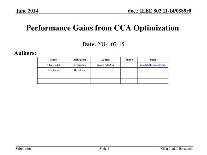
Performance Gains from CCA Optimization. Date: 2014-07-15. Authors:. Overview. Earlier IEEE contributions [1][2] provided PHY system simulation results showing performance gains (mean and 5% per-STA throughput) from CCA optimization, for simulation scenario 1

E N D
Performance Gains from CCA Optimization Date:2014-07-15 Authors: Nihar Jindal, Broadcom
Overview Earlier IEEE contributions [1][2] provided PHY system simulation results showing performance gains (mean and 5% per-STA throughput) from CCA optimization, for simulation scenario 1 Here we provide results showing significant CCA optimization gains for simulation scenarios 1, 2, and 3, with a focus on scenario 2 Nihar Jindal, Broadcom
Simulation Parameters • 26 dBm AP, 18 dBm STA • All results are for 1x1 • Chose above numbers to reflect 4 antenna AP with 20 dBm per AP antenna and 2 antenna STA with 15 dBm per antenna • Downlink only • 5 GHz, 80 Mhz channels • NF = 7 dB -> noise floor of -88 dBm • Effective SNR computed using Shannon capacity • Essentially equal to geometric mean of SNR (i.e., linear average of per-tone dB SINR) • Genie MCS, with following required SNR’s per MCS: Nihar Jindal, Broadcom
Scenario 2: Wireless Office 4x2 office layout Office layout (4 AP’s, 64 cubicles) • 8 offices in 4x2 configuration, and each office has 4 AP’s (uniformly spaced) and 128 STAs (2 STAs per cube, 64 cubes per office) • 5 GHz, 80 MHz, 4 channels with fixed channelization pattern per office • 11nD PL + 11nD NLOS multipath + 4 dB iidshadow + 7 dB wall Nihar Jindal, Broadcom
S2: Performance vs. CCA (AWGN, no shadow) • Mean and 5% throughput monotonically increase with CCA, and see gains of 3.5X and 4X, respectively Nihar Jindal, Broadcom
S2: Geometry 20m 4 1 2 4 1 2 4 1 2 4 1 2 4 1 2 4 1 2 4 1 2 4 1 2 20m • Due to fixed channelization and fixed AP locations, distance between co-channel AP’s is 20m (+ 7 dB/wall) -> 84 dB PL • 1 wall separated APs: -58 dBm, Diagonally separated: -70 dBm • 2 wall: -76 dBm, 2 wall + diagonal: -84.6 dBm • 3 wall: -89 dBm, 3 wall + diagonal: -97 dBm • Distance from STA to nearest AP ranges from 2.1m to 6.67m • Vertical distance is always 1.5m due to AP on ceiling (3m) versus STA at 1m • Corresponding PL range is 53 dB to 63 dB, so RX power range is -27 dBm to -37 dBm • 4 distinct CCA regimes with 18.75%, 25%, 45%, and 100% of AP’s on • Worst-case SINR with all AP’s on is 14.4 dB Nihar Jindal, Broadcom
S2: Effect of Shadowing and Fading • Shadowing and fading smooth out curves, but trends are similar to AWGN no shadowing • Key difference is in 5% tput: for no shadowing increases monotonically with CCA, whereas with shadowing/fading see a peak in 5% tput around -70 dBm • Shadowing rather than fading is the big difference maker Nihar Jindal, Broadcom
BSS BS BSS BSS BSS BSS BSS BSS BSS BSS BSS BSS BSS BSS BSS BSS BSS BSS BSS Scenario 3: Indoor Small BSS Reuse 1 Reuse 3 Nihar Jindal, Broadcom • Hexagonal cells with ICD = 17.32 m (R = 10m) • 11nD PL (bp = 10m) + 11nD NLOS multipath + 4 dB iid shadowing • Identical to S2 • Reuse 3 and reuse1
S3 (reuse 3): Performance vs. CCA • Similar to S2, AWGN no shadowing displays monotonically increasing mean and 5% tput, but the addition of shadowing/fading leads to 5% tput peaking around -70 dBm • Both S2 and S3 (reuse3) have fixed reuse patterns that lead to a guaranteed (in absence of shadowing) high SINR at cell edge Nihar Jindal, Broadcom
S3 (reuse 1): Performance vs. CCA • >2X gains in mean tput, but smaller gain in 5% tput • 5% tput drops to zero for very aggressive CCA threshold Nihar Jindal, Broadcom
Scenario 1 - Residential • 100 apartments, 20 per floor (2x10), 5 floors. 10x10x3m dimensions • 5 GHz, each BSS randomly picks 1 of 3 80 MHz channels • One AP and 10 STA’s per apartment • STA always associates to AP inside same apartment • Every device randomly located within apartment • 11nB PL + 11nD NLOS multi-path + 4 dB iid shadow • 5 dB loss per wall (linear sum), 18.3 dB/floor (nonlinear sum) Nihar Jindal, Broadcom
S1 with 3 channels: Performance vs. CCA • Mean tput peaks with CCA around -55 dBm, whereas 5% tput peaks at ~ -70 dBm Nihar Jindal, Broadcom
S1 with 1 channel: Performance vs. CCA • Similar trends as 3 channel S1, but even larger gains Nihar Jindal, Broadcom
Summary • CCA optimization provides very significant gains for simulation scenarios 1, 2, and 3, in terms of mean and 5% throughput • 2X or greater feasible in many scenarios • Scenario 4 still under investigation, although expect smaller gains due to large cell size • Optimal CCA threshold for 5% throughput is generally 10-20 dB lower than optimal threshold for mean throughput • Overly aggressive reuse can benefit BSS-interior users at the expense of BSS-exterior users • Dynamic CCA threshold selection still an open problem • Because interference-limited, changing bandwidth or band has little effect on results: • Going from 5G to 2.4G leads to ~ 6 dB less path loss, which essentially shifts performance vs. CCA curves by 6 dB Nihar Jindal, Broadcom
References [1] “Improved Spatial Reuse Feasibility – Part I”, IEEE 802.11-14/0082r0 [2] “Improved Spatial Reuse Feasibility – Part II”, IEEE 802.11-14/0083r0 Nihar Jindal, Broadcom