Download
1 / 24
280 likes | 776 Views
《气动技术》双语电子教案 吴洪明 Chapter 8 Sensor. Switches and Sensors. For integrated control systems. WUHAN UNIVERSITY OF TECHNOLOGY LOGISTICS ENG. DEPT. 武汉理工大学 物流工程学院. 《气动技术》双语电子教案 吴洪明 Chapter 8 Sensor. Contents. Introduction. Cable capacitance. Vacuum electric switch.

E N D
《气动技术》双语电子教案 吴洪明 Chapter 8 Sensor Switches and Sensors For integrated control systems WUHAN UNIVERSITY OF TECHNOLOGY LOGISTICS ENG. DEPT. 武汉理工大学 物流工程学院
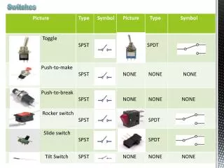
《气动技术》双语电子教案 吴洪明 Chapter 8 Sensor Contents • Introduction • Cable capacitance • Vacuum electric switch • Magnetic cylinders • Reed switch principle • Vacuum electronic switch • Sensor principle • QM/45/* range • QM/33,34,134 range • M/40,41,42 range • Inductive proximity sensors Click the section to advance directly to it
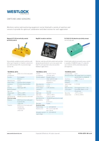
Typical electro-pneumatic systems consist of: magnetic cylinders and solenoid valves for dynamic power reed switches and sensors for feedback electronic logic for control Reed switches and solid state magnetic sensors are fitted to cylinders to feedback particular positions of the piston Solid state proximity sensors can be used to replace limit switches, for detecting the position of mechanisms or other moving parts Reed switches and solid state sensors are small, fast, easy to fit and adjust. They simplify installation on to the machine application 《气动技术》双语电子教案 吴洪明 Chapter 8 Sensor Introduction
《气动技术》双语电子教案 吴洪明 Chapter 8 Sensor Magnetic cylinders • Magnetic cylinders have a band of magnetic material inset around the circumference of the piston • The polarity is in parallel with the axis of the cylinder • The barrel is made of non ferrous material • By placing reed switches along the outside of the cylinder, signals can be given at the extreme and intermediate positions of stroke Click the illustration to start and stop animation
《气动技术》双语电子教案 吴洪明 Chapter 8 Sensor Reed switch principle • A basic reed switch consists of a small glass tube containing soft iron contact reeds normally sprung open • When a magnetic field is in range the reeds will become magnetic • The ends will be of opposite polarity and pull themselves together Click the illustration to start and stop animation
N S 《气动技术》双语电子教案 吴洪明 Chapter 8 Sensor Magnetic sensor principle • In the presence of a magnetic field the magnetoresistive sensor has a lower resistance. This causes current to be drawn from the base of the transistor turning it on • The circuit incorporates l.e.d., reverse polarity protection diodes and suppression diode for an inductive load +V load 0V sensor
《气动技术》双语电子教案 吴洪明 Chapter 8 Sensor Reed switches and sensor • Slim cylindrical housing • PVC cable in 2 or 5 metre lengths • Optional very flexible polyurethane cable • With or without l.e.d. indicator • Range of four reed switches and one solid state sensor
Protection diode for d.c. only 0 V QM/45/RAP Blue Coil + V Brown 《气动技术》双语电子教案 吴洪明 Chapter 8 Sensor Reed switches • Basic reed switch • Shown connected to a relay or solenoid coil with diode suppression for d.c. application • 10 to 30V a.c./d.c. • Maximum switching power 10 W/VA
Protection diode 0 V QM/45/LAP Black Coil Blue 0 V + V Brown 《气动技术》双语电子教案 吴洪明 Chapter 8 Sensor Reed switches • Reed switch with l.e.d. indicator • Three wires emulating p.n.p. sensor • Current sourced on the black wire to the coil • Resistor protects l.e.d. from over voltage
Voltage dependant resistor (VDR) QM/45/LAP 0 V Blue Coil + V Brown 《气动技术》双语电子教案 吴洪明 Chapter 8 Sensor Reed switches • Reed switch with l.e.d. indicator and two wires only • Current sourced on the black wire to the coil • Zener diode provides small voltage drop to turn on l.e.d. • 10 to 240V a.c./170V d.c. 10 W/VA maximum • Shown with VDR for suppression a.c. or d.c.
Protection diode + V QM/45/LAN Black Load + V Brown Blue 0 V 《气动技术》双语电子教案 吴洪明 Chapter 8 Sensor Reed switches • Reed switch with l.e.d. indicator • Three wires emulating n.p.n. sensor • Current sunk on the blue wire from the load to 0V • Resistor protects l.e.d. from over voltage
QM/45/EAP +V brown blue 0V coil pnp 0V black protection diode 《气动技术》双语电子教案 吴洪明 Chapter 8 Sensor Solid state switches • Solid state magnetically operated p.n.p. output • Used for applications where vibration levels are unsuitable for reed switches • Magnetoresistive sensor element • ‘Sensor on’ l.e.d. indicator • 10 to 30 V d.c. 200mA maximum
《气动技术》双语电子教案 吴洪明 Chapter 8 Sensor Reed switches and sensors • Neat cylindrical housing with fixed or plug-in cable • Straight or 90o plug-in connector cables • Optional: very flexible polyurethane cable or high temperature (150oC) silicon cable • With or without l.e.d. indicator • Wide range of reed switches and solid state sensors
brown +V QM/33 Load blue 0V black 0V Load blue QM/33/C 0V Load brown +V brown +V blue 0V QM/34/P Load black 0V blue 0V brown +V QM/34/N Load black +V brown +V QM/34/S blue 0V Load 《气动技术》双语电子教案 吴洪明 Chapter 8 Sensor Reed switches • Plain reed switch • Plain change-over reed switch • Three wire reed switch with l.e.d., emulating p.n.p. sensor and plug-in cable • Three wire reed switch with l.e.d., emulating n.p.n. sensor • Two wire reed switch with l.e.d.
brown +V blue 0V pnp black 0V Load 1 brown +V 3 blue 0V pnp 4 black 0V Load blue 0V brown +V npn black +V Load blue 0V 3 brown +V npn 4 black +V Load brown +V blue 0V 《气动技术》双语电子教案 吴洪明 Chapter 8 Sensor Solid state sensors QM/134 • Output p.n.p. fixed cable • Output p.n.p. plug-in cable • Output n.p.n. fixed cable • Output n.p.n. plug-in cable • Pulse stretcher. Output p.n.p. fixed cable. When operated and released output will remain on for a further 30 ms approximately. Suitable for part stroke position on fast operating cylinders QM/134/P QM/134/N 1 QM/134/N/P QM/134/X black 0V Load
《气动技术》双语电子教案 吴洪明 Chapter 8 Sensor Reed switches and sensors • Low profile with dove tail slide for cylinders with integral track in extruded body • Screw tightening • Fixed cable or plug-in connector cables straight or 90o • With or without l.e.d.
《气动技术》双语电子教案 吴洪明 Chapter 8 Sensor Reed switches and sensors • Low profile with dove tail slide for cylinders with integral track in extruded body • Screw tightening • Fixed cable or plug-in connector cables straight or 90o • With or without l.e.d.
brown +V blue 0V Load brown +V 0V Load blue black 0V Load blue 0V Load brown +V 《气动技术》双语电子教案 吴洪明 Chapter 8 Sensor Reed switches M/40 • Two wire with l.e.d. 10 to 240V a.c./170V d.c. • With high temperature cable • With very flexible polyurethane cable • Two wire with l.e.d. and plug in cable 10 to 60V a.c./74 d.c. • Change-over contacts without l.e.d. TM/40 M/40/*/PU M/40/P M/40/C
blue 0V M/41 brown +V npn black +V Load brown +V blue 0V M/42 pnp black 0V Load M/42/*/PU 1 brown +V 3 blue 0V M/42/P pnp 4 black 0V Load 《气动技术》双语电子教案 吴洪明 Chapter 8 Sensor Solid state magnetic switches • Output n.p.n. 10 to 30V d.c. 200 mA maximum • Output p.n.p. 10 to 30V d.c. 200 mA maximum • Output p.n.p. with very flexible polyurethane cable • Output p.n.p. with plug-in cable
M/P28473 M/P70104/1&2 M/P70104/3&4 M/P70104/5&6 M/P70104/7&8 M/P70104/9 brown brown +V +V pnp pnp blue blue 0V 0V Load Load black black 《气动技术》双语电子教案 吴洪明 Chapter 8 Sensor Inductive proximity sensors • Sense the presence of metal near the tip • Used as a limit switch for mechanical parts • Depending on type: • Range 0.8 to 2 mm • Switching frequency 500 to 2000 Hz • With or without l.e.d. • 10 to 30 or 6 to 30 V d.c. • Normally closed or normally open p.n.p. output • output
+ V 0 V + V 0 V 470µH L + V Load 0 V Standard leads Extended leads 《气动技术》双语电子教案 吴洪明 Chapter 8 Sensor Cable capacitance • Long leads above the standard cable length become a long thin capacitor (equivalent circuit) • Closing the switch shorts the capacitor, the instant high current overloads and damages the switch contacts • Fit an inductor (470µH)close to the switch. This damps the surge but has a low steady state resistance
《气动技术》双语电子教案 吴洪明 Chapter 8 Sensor Vacuum electric switch • Switches contacts at a vacuum set point • Adjustable between zero and 0.8 bar absolute • Normally open and normally closed versions • Up to 250V a.c./d.c. 2A max • Repeatability + or - 0.1 bar • Reset differential 0.2 bar
set point hysteresis +V dc supply (brown) Analog out (white) Switch out (black) 0 V (blue) U Load +V dc supply (brown) Analog out (white) Switch out (black) 0 V (blue) U Load 《气动技术》双语电子教案 吴洪明 Chapter 8 Sensor Vacuum solid state switch • Analogue output 1 to 5 V proportional to vacuum • Solid state switched output at vacuum set point • Adjustable reset hysteresis • Adjustable from zero to 1bar absolute • Output n.p.n. or p.n.p. vesions
《气动技术》双语电子教案 吴洪明 Chapter 8 Sensor End