Download
1 / 63
630 likes | 672 Views
This introduction to hydraulics of open channels covers basic concepts, conservation laws, critical flows, uniform flows, gradually varied flows, rapidly varied flows, and unsteady flows. It discusses the flow of water in open channels, pressure, velocity head, conservation of mass, momentum, and energy. Various types of open channel flows such as sub-critical, super-critical, critical, steady, unsteady, uniform, gradually varied, and rapidly varied flows are explained. Definitions of specific energy and specific force are provided, along with discussions on critical flow and its characteristics. This resource is essential for understanding the principles of hydraulics in open channel systems.

E N D
Introduction to Hydraulics of Open Channels By Parveen Kumar
Topics to be covered • Basic Concepts • Conservation Laws • Critical Flows • Uniform Flows • Gradually Varied Flows • Rapidly Varied Flows • Unsteady Flows
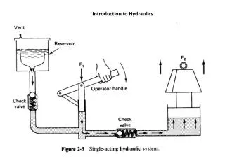
Basic Concepts • Open Channel flows deal with flow of water in open channels • Pressure is atmospheric at the water surface and the pressure is equal to the depth of water at any section • Pressure head is the ratio of pressure and the specific weight of water • Elevation head or the datum head is the height of the section under consideration above a datum • Velocity head (=v2/2g) is due to the average velocity of flow in that vertical section
Basic Concepts Cont… The flow of water in an open channel is mainly due to head gradient and gravity Open Channels are mainly used to transport water for irrigation, industry and domestic water supply
Conservation Laws The main conservation laws used in open channels are
Conservation of Mass Conservation of Mass In any control volume consisting of the fluid ( water) under consideration, the net change of mass in the control volume due to inflow and out flow is equal to the the net rate of change of mass in the control volume This leads to the classical continuity equation balancing the inflow, out flow and the storage change in the control volume. Since we are considering only water which is treated as incompressible, the density effect can be ignored
Conservation of Momentum and energy Conservation of Momentum This law states that the rate of change of momentum in the control volume is equal to the net forces acting on the control volume Since the water under consideration is moving, it is acted upon by external forces Essentially this leads to the Newton’s second law Conservation of Energy This law states that neither the energy can be created or destroyed. It only changes its form.
Conservation of Energy Mainly in open channels the energy will be in the form of potential energy and kinetic energy Potential energy is due to the elevation of the water parcel while the kinetic energy is due to its movement In the context of open channel flow the total energy due these factors between any two sections is conserved This conservation of energy principle leads to the classical Bernoulli’s equation P/γ + v2/2g + z = Constant When used between two sections this equation has to account for the energy loss between the two sections which is due to the resistance to the flow by the bed shear etc.
Types of Open Channel Flows Depending on the Froude number (Fr)the flow in an open channel is classified as Sub critical flow, Super Critical flow, and Critical flow, where Froude number can be defined as
Types of Open Channel Flow Cont… Steady Flow Flow is said to be steady when discharge does not change along the course of the channel flow Unsteady Flow Flow is said to be unsteady when the discharge changes with time Uniform Flow Flow is said to be uniform when both the depth and discharge is same at any two sections of the channel
Types of Open Channel Cont… Gradually Varied Flow Flow is said to be gradually varied when ever the depth changes gradually along the channel Rapidly varied flow Whenever the flow depth changes rapidly along the channel the flow is termed rapidly varied flow Spatially varied flow Whenever the depth of flow changes gradually due to change in discharge the flow is termed spatially varied flow
Types of Open Channel Flow cont… Unsteady Flow Whenever the discharge and depth of flow changes with time, the flow is termed unsteady flow
Definitions Specific Energy It is defined as the energy acquired by the water at a section due to its depth and the velocity with which it is flowing Specific Energy E is given by, E = y + v2/2g Where y is the depth of flow at that section and v is the average velocity of flow Specific energy is minimum at critical condition
Definitions Specific Force It is defined as the sum of the momentum of the flow passing through the channel section per unit time per unit weight of water and the force per unit weight of water F = Q2/gA +yA • The specific forces of two sections are equal provided that the external forces and the weight effect of water in the reach between the two sections can be ignored. • At the critical state of flow the specific force is a minimum for the given discharge.
Critical Flow Flow is critical when the specific energy is minimum. Also whenever the flow changes from sub critical to super critical or vice versa the flow has to go through critical condition figure is shown in next slide Sub-critical flow-the depth of flow will be higher whereas the velocity will be lower. Super-critical flow-the depth of flow will be lower but the velocity will be higher Critical flow: Flow over a free over-fall
Characteristics of Critical Flow Specific Energy (E = y+Q2/2gA2) is minimum For Specific energy to be a minimum dE/dy = 0 However, dA=Tdy, where T is the width of the channel at the water surface, then applying dE/dy = 0, will result in following
Characteristics of Critical Flow • For a rectangular channel Ac /Tc=yc • Following the derivation for a rectangular channel, • The same principle is valid for trapezoidal and other cross sections • Critical flow condition defines an unique relationship between depth and discharge which is very useful in the design of flow measurement structures
Uniform Flows This is one of the most important concept in open channel flows The most important equation for uniform flow is Manning’s equation given by Where R = the hydraulic radius = A/P P = wetted perimeter = f(y, S0) Y = depth of the channel bed S0= bed slope (same as the energy slope, Sf) n = the Manning’s dimensional empirical constant
Uniform Flow Example : Flow in an open channel This concept is used in most of the open channel flow design The uniform flow means that there is no acceleration to the flow leading to the weight component of the flow being balanced by the resistance offered by the bed shear In terms of discharge the Manning’s equation is given by
Uniform Flow This is a non linear equation in y the depth of flow for which most of the computations will be made Derivation of uniform flow equation is given below, where = weight component of the fluid mass in the direction of flow = bed shear stress = surface area of the channel
Uniform Flow • The force balance equation can be written as • Or • Or • Now A/P is the hydraulic radius, R, and sinθis the slope of the channel S0
Uniform Flow • The shear stress can be expressed as • Where cf is resistance coefficient, V is the mean velocity ρis the mass density • Therefore the previous equation can be written as • Or • where C is Chezy’s constant • For Manning’s equation
Gradually Varied Flow Flow is said to be gradually varied whenever the depth of flow changed gradually The governing equation for gradually varied flow is given by Where the variation of depth y with the channel distance x is shown to be a function of bed slope S0, Friction Slope Sf and the flow Froude number Fr. This is a non linear equation with the depth varying as a non linear function
Gradually Varied Flow Derivation of gradually varied flow is as follows… • The conservation of energy at two sections of a reach of length Δx, can be written as • Now, let and Then the above equation becomes
Gradually Varied Flow • Dividing through Δx and taking the limit as Δx approaches zero gives us • After simplification, • Further simplification can be done in terms of Froude number
Gradually Varied Flow • After differentiating the right side of the previous equation, • But dA/dy=T, and A/T=D, therefore, • Finally the general differential equation can be written as
Gradually Varied Flow Numerical integration of the gradually varied flow equation will give the water surface profile along the channel Depending on the depth of flow where it lies when compared with the normal depth and the critical depth along with the bed slope compared with the friction slope different types of profiles are formed such as M (mild), C (critical), S (steep) profiles. All these have real examples. M (mild)-If the slope is so small that the normal depth (Uniform flow depth) is greater than critical depth for the given discharge, then the slope of the channel is mild.
Gradually Varied Flow • C (critical)-if the slope’s normal depth equals its critical depth, then we call it a critical slope, denoted by C • S (steep)-if the channel slope is so steep that a normal depth less than critical is produced, then the channel is steep, and water surface profile designated as S
Rapidly Varied Flow • This flow has very pronounced curvature of the streamlines • It is such that pressure distribution cannot be assumed to be hydrostatic • The rapid variation in flow regime often take place in short span • When rapidly varied flow occurs in a sudden-transition structure, the physical characteristics of the flow are basically fixed by the boundary geometry of the structure as well as by the state of the flow Examples: • Channel expansion and cannel contraction • Sharp crested weirs • Broad crested weirs
Unsteady flows • When the flow conditions vary with respect to time, we call it unsteady flows. • Some terminologies used for the analysis of unsteady flows are defined below: • Wave: it is defined as a temporal or spatial variation of flow depth and rate of discharge. • Wave length: it is the distance between two adjacent wave crests or trough • Amplitude: it is the height between the maximum water level and the still water level
Unsteady flows definitions • Wave celerity (c): relative velocity of a wave with respect to fluid in which it is flowing with V • Absolute wave velocity (Vw): velocity with respect to fixed reference as given below • Plus sign if the wave is traveling in the flow direction and minus for if the wave is traveling in the direction opposite to flow • For shallow water waves where y0=undisturbed flow depth.
Unsteady flows examples Unsteady flows occur due to following reasons: • Surges in power canals or tunnels • Surges in upstream or downstream channels produced by starting or stopping of pumps and opening and closing of control gates • Waves in navigation channels produced by the operation of navigation locks • Flood waves in streams, rivers, and drainage channels due to rainstorms and snowmelt • Tides in estuaries, bays and inlets
Unsteady flows • Unsteady flow commonly encountered in an open channels and deals with translatory waves. Translatory waves is a gravity wave that propagates in an open channel and results in appreciable displacement of the water particles in a direction parallel to the flow • For purpose of analytical discussion, unsteady flow is classified into two types, namely, gradually varied and rapidly varied unsteady flow • In gradually varied flow the curvature of the wave profile is mild, and the change in depth is gradual • In the rapidly varied flow the curvature of the wave profile is very large and so the surface of the profile may become virtually discontinuous.
Unsteady flows cont… • Continuity equation for unsteady flow in an open channel • For a rectangular channel of infinite width, may be written • When the channel is to feed laterally with a supplementary discharge of q’ per unit length, for instance, into an area that is being flooded over a dike
Unsteady flows cont… • The equation • The general dynamic equation for gradually varied unsteady flow is given by:
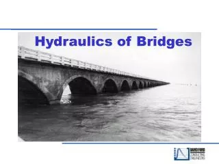
Contents • General introduction • Energy equation • Head loss equations • Head discharge relationships • Pipe transients flows through pipe networks • Solving pipe network problems
General Introduction • Pipe flows are mainly due to pressure difference between two sections • Here also the total head is made up of pressure head, datum head and velocity head • The principle of continuity, energy, momentum is also used in this type of flow. • For example, to design a pipe, we use the continuity and energy equations to obtain the required pipe diameter • Then applying the momentum equation, we get the forces acting on bends for a given discharge
General introduction • In the design and operation of a pipeline, the main considerations are head losses, forces and stresses acting on the pipe material, and discharge. • Head loss for a given discharge relates to flow efficiency; i.e an optimum size of pipe will yield the least overall cost of installation and operation for the desired discharge. • Choosing a small pipe results in low initial costs, however, subsequent costs may be excessively large because of high energy cost from large head losses
Energy equation • The design of conduit should be such that it needs least cost for a given discharge • The hydraulic aspect of the problem require applying the one dimensional steady flow form of the energy equation: Where p/ =pressure head V2/2g =velocity head z =elevation head hp=head supplied by a pump ht =head supplied to a turbine hL =head loss between 1 and 2
Energy equation Velocity head • In V2/2g, the velocity V is the mean velocity in the conduit at a given section and is obtained by V=Q/A, where Q is the discharge, and A is the cross-sectional area of the conduit. • The kinetic energy correction factor is given by , and it is defines as, where u=velocity at any point in the section • has minimum value of unity when the velocity is uniform across the section
Energy equation cont… Velocity head cont… • has values greater than unity depending on the degree of velocity variation across a section • For laminar flow in a pipe, velocity distribution is parabolic across the section of the pipe, and has value of 2.0 • However, if the flow is turbulent, as is the usual case for water flow through the large conduits, the velocity is fairly uniform over most of the conduit section, and has value near unity (typically: 1.04< < 1.06). • Therefore, in hydraulic engineering for ease of application in pipe flow, the value of is usually assumed to be unity, and the velocity head is then simply V2/2g.
Energy equation cont… Pump or turbine head • The head supplied by a pump is directly related to the power supplied to the flow as given below • Likewise if head is supplied to turbine, the power supplied to the turbine will be • These two equations represents the power supplied directly or power taken out directly from the flow
Energy equation cont… Head-loss term • The head loss term hL accounts for the conversion of mechanical energy to internal energy (heat), when this conversion occurs, the internal energy is not readily converted back to useful mechanical energy, therefore it is called head loss • Head loss results from viscous resistance to flow (friction) at the conduit wall or from the viscous dissipation of turbulence usually occurring with separated flow, such as in bends, fittings or outlet works.
Head loss calculation • Head loss is due to friction between the fluid and the pipe wall and turbulence within the fluid • The rate of head loss depend on roughness element size apart from velocity and pipe diameter • Further the head loss also depends on whether the pipe is hydraulically smooth, rough or somewhere in between • In water distribution system , head loss is also due to bends, valves and changes in pipe diameter