Download
1 / 54
550 likes | 759 Views
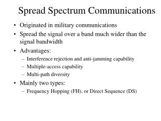
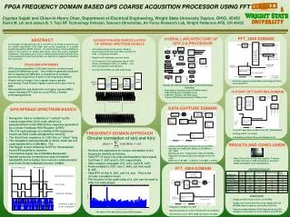
Spread Spectrum Signals in Modern Communications. Jan Šimša Institute of Radio Engineering and Electronics AS CR simsa @ure.cas.cz. What signal has spread spectrum ?. Any digitally modulated signal whose ratio of bandwidth to its data (modulation) symbol rate

E N D
Spread Spectrum Signals in Modern Communications Jan Šimša Institute of Radio Engineering and Electronics AS CR simsa@ure.cas.cz Radioelektronika 2005
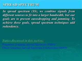
What signal has spread spectrum? • Any digitally modulated signal whose ratio of bandwidth to its data (modulation) symbol rate is substantially greater than one. Spreading of spectrum – generation of signal using shaping or modulation Radioelektronika 2005
Contents • Motivation • Classification of signals and methods of spreading spectrum • Features of SS signals • Optimum reception (detection) • Synchronization • Code division multiplex (multiple access) • Conclusions Radioelektronika 2005
Motivation No (user) Why is spreading utilized? • Transmission of an additional information? • Decrease of error rate in AWGN channel? • ????? • Decrease of error rate in any more disturbing channel? • Preserving of unauthorized reception? • Advantageous multiple utilization of a channel? What is the price we pay for these advantageous features? Complexity of a system realization No Yes Yes Yes Radioelektronika 2005
Heavily distorting communication channels • Time variant channels • Multipath channels • Frequency selective channels • Channels with interferences Radioelektronika 2005
Frequency diversity • Frequency selective / nonselective channels • Channel coherence bandwidth is given by parameters of the channel • Narrowband signals can fade completely • Frequency nonselective selective Radioelektronika 2005
Frequency diversity • Distortion by frequency selective channel • One deep fade model – rectangular fade Radioelektronika 2005
Frequency diversity • Impulse responseofthe rectangular fade Responseto one chip of the rectangular shape Radioelektronika 2005
Frequency diversity Response y1i(t) to positive chip for B.Tc = 0.01 (solid line ) B.Tc = 0.05 (dotted line) Radioelektronika 2005
Classification of signals and methods of spreading spectrum • Any spread spectrum signal belongs to one of the three categories: • signals without a carrier • signals with a single carrier • signals with multiple carriers Radioelektronika 2005
Signals without carrier • are created by a sequence of very narrow pulses (< 1ns) of a proper shape(Gaussian, wavelets) • their spectrum bandwidth is by some orders of magnitude wider than the modulation rate. Such signals are often referred to as Ultra Wide-Band (UWB) signals (and related UWB systems). Their bandwidth B≥500 MHz, B/f0 ≥ 0.2 • it can reach bandwidth > 5 GHz Radioelektronika 2005
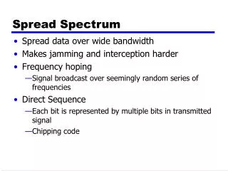
Single carrier signals • Harmonic carrier spread spectrum (SS) signals • three basic subgroups • Direct Sequence (DS) – spreading by BPSK, QPSK keying • Frequency Hopping (FH) • Time Hopping (TH) - slow (SFH) - fast (FFH) Radioelektronika 2005
Direct Sequence (DS) Spreading Radioelektronika 2005
Direct Sequence (DS) Spreading Radioelektronika 2005
Direct Sequence (DS) Spreading Radioelektronika 2005
Direct Sequence Spreading Radioelektronika 2005
Direct Sequence Spreading Radioelektronika 2005
Direct Sequence Spreading Radioelektronika 2005
Direct Sequence Spreading • BPSK data modulation b(t) and BPSK spreading modulation c(t) Spreading modulation c(t) Data modulation b(t) where T- symbol interval, Tc- chip interval The period of spreading modulation is T=L.Tc Radioelektronika 2005
Optimization of linearreceiver • Matched filter (MF) – correlator Its response MF impulse response is defined by the signal to which MF is matched - MF[s(t)] MF response at t=t0=T to finite signal s(t) whose interval of nonzero values is (0,T),is Radioelektronika 2005
Optimization of linear receiver • MF • correlator Radioelektronika 2005
Interferences • Response of MF[s(t)] to interfering signal s1 • Correlation coef. • Orthogonal signals do not cause any interference • Correlation in time domain – frequency domain • Parseval’s formula Orthogonal signals have orthogonal spectra Radioelektronika 2005
Code synchronization • Code synchronization is an alignment of the spreading modulation of received signal and the replica at the multiplier producing despreaded signal • It consists of two steps • Acquisition – coarse alignment of the modulation and the replica • Tracking – accurate alignment and time-variations tracking Radioelektronika 2005
DS Code acquisition with the aid of a system of correlators - Matched filters Uncertainty region – the interval of prospective alignments. The position is nonsensitive to shifts by an integer multiple of the spreading signal period (modulo L.Tc ) The goal (penalty) function of code acquisition process optimization • Mean acquisition time – minimization • Probability of acquisition within given time interval – max Code acquisition process is defined • by acquisition detector rule • by search strategy - a sequence of points defining the replica positions within an uncertainty region Classification according to changes of replica position • Stepping correlator • Sliding correlator Radioelektronika 2005
Classification of DS code acquisitiondetectors as to the number of channels • Single channeldetector – for serial search on uncertainty region • Multiple channeldetector – for parallel / serio-parallel search as to the realization of each channel of the detector • Passive correlator - multiplier/integrator • Active correlator - Matched Filter (DSP, SAW) as to the rule of the final decision making • Single dwell detector • Multiple dwell detector Radioelektronika 2005
Spreading signal - optimization • Sharp and narrow main lobe of autocorrelation • DC component-free • Low- level side lobes of autocorrelation • Long linear span • Low croscorrelation between signal and interferences • Generating constant- envelope signal • Noise-like signals – pseudonoise (PN) signals • M-sequences, Gold codes, Kasami codes, Walsh Hadamard sequences, bent sequences, Radioelektronika 2005
Slow Frequency Hopping Radioelektronika 2005
Slow Frequency Hopping Radioelektronika 2005
Fast Frequency Hopping Radioelektronika 2005
Time hopping • Packet transmission • Fixed length of packets • Pseudorandom position of packets within frame • Position control by code sequence Radioelektronika 2005
Two-path channel Radioelektronika 2005
Multipath channel – Rake receiver Radioelektronika 2005
Interferences • Orthogonal signals do not cause interferences (orthogonality is not generally invariant to mutual shift of signals) • Nonorthogonal (correlated) signals cause interference • Interference is proportional to amplitude of interfering signal • This amplitude can be greater than the amplitude of useful (target) signal = near-far effect Efekt nestejných vzdáleností (efekt nestejných amplitud) Radioelektronika 2005
Multicarrier CDMA TN = T, = fi+1 – fi =(i+1-i)/2 = T-1 Components are orthogonal on the interval T Radioelektronika 2005
Multicarrier DS CDMA TN = T/N , = fi+1 – fi =(i+1-i)/2 =Tc-1 Components are orthogonal on the interval Tc Radioelektronika 2005
Multitone CDMA TN = N.T, = fi+1 – fi =(i+1-i)/2 =(N• T)-1 Components are orthogonal on the interval TN Radioelektronika 2005
Comparison in frequency domain Radioelektronika 2005
Shared communication channel • Multiplex (Multiple Access) • Frequency division • Time division • Code division Timing of symbols – identical =synchronous CDMA - nonidentical = symbol asynchronous CDMA > identical chip timing = chip synchronous CDMA > nonidentical chip timing = chip asynchronous Radioelektronika 2005
Code Division Multiple Access Signal space - dimensionality 2BT = number of mutually orthogonal signals Radioelektronika 2005
Synchronous and Asynchronous CDMA Radioelektronika 2005
CDMA signal • Signal at detector input where bi(t) is data signal of the i-th user, is its delay and si(t) is its spreading modulation, which in CDMA is labeled to as a signature. Usually, signature has unit energy ( a system of orthogonal signatures is in the same time orthonormal). As ci2(t)=1, the unit energy signature si(t) is preserved if Radioelektronika 2005
Synchronous CDMA • CDMA is synchronous, iff Without loss of generality let it be Then This signal causes response ym of MF matched to the signature of m-th user MUI Radioelektronika 2005
Multiuser interference (MUI) The second component of the right side of the equation representsMultiuser Interference (MUI / MAI) This component is zero if the signatures at the detector input are ortogonal. If system designer is not able ensure validity of this condition (it is the usual case as parameters of channel are unknown and time variable) Detector minimizing MUI is not MF any more; it is more complex, usually nonlinear. To keep the complexity of receiver acceptably low, suboptimum linear detectors are used. Radioelektronika 2005
Multiuser detection • Vector notation • Matrix of amplitudes and correlation matrix Vector y can now be expressed as Detector estimates vector of data Optimum detector is described by the equation Radioelektronika 2005
It can be expressed using likelihood where and Averaging over random variable bkis not performed . For a priori equiprobable symbols the above average is Optimum receiver is nonlinear. Radioelektronika 2005
Linear detectors Using vector notation it is where Approximation ofthe optimum detector - linear detectors Linear detector consists of the bank of filters matched to the signatures of individual users and weighted sum of their outputs is created. Weights in summation are chosen in a way minimizing MUIor noise plus MUI, respectively. Radioelektronika 2005
Block diagram of linear multiuser detector Radioelektronika 2005
Conventional detector Conventional detector – bank of MFs This detector is optimum in the case of uncorrelated signatures, i.e. if If signatures are correlated, MAI is nonzero. Radioelektronika 2005
Decorrelating detector • Matrix M is the inverse to correlation matrix R Then and k-th component of the detector output is MUI component is totally compensated but noise component has increased. Radioelektronika 2005
MMSE detector It minimizes men square error of the vector b estimate. We search for the matrix M minimizing this error where the norm of vector is defined as After some manipulation Radioelektronika 2005